 ช้างเผือก
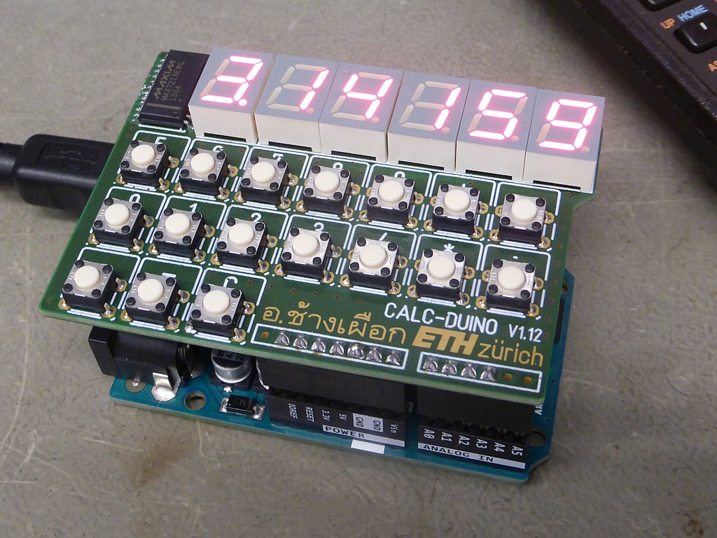
Categories
Statistics
Since 08.08.2014
Counts only, if "DNT = disabled".
Your IP is 18.218.38.125
ec2-18-218-38-125.us-east-2.
Counts only, if "DNT = disabled".
Your IP is 18.218.38.125
ec2-18-218-38-125.us-east-2.
Info

เราจะทำแบบวิศวกรผู้ยิ่งใหญ่

25. April 2024
Your valuable opinion :
Arduino-CALCDUINO.php 13118 Bytes 31-05-2023 13:02:55
ARDUINO/Genuino 'Pocket Calculator' Shield
1960's performance, build with year 2016 technology :-)
Designed to make students think about mathematics and how it may be adressed in
programming a microcontroller. Thanks to the arduino community, there already exist libraries for scanning
a matrix keypad, as well as handling a MAX7219.
✈ Hardware Description
As with other data processing units, we may identify three function blocks. The input is handled by the arduino uno shield. It consists
of scanning the matrix keyboard (4 rows x 4 columns). So is the processing done. The output is then handled by six 7-segment led's, driven by a
MAX7219. A single serial bitstream is necessary to transfer all the information to it. It then scans the digits/segments automatically.
As we used 17 keys, the "CLEAR" key does reset the arduino, whilst the other 16 keys form the matrix. Therefore the setup routine should
clear all variables. Don't forget to assemble three components on the bottom layer !


✈ MAX7219 (MAX7221)
The MAX7219 is unquestionably the working horse of this shield. They "are compact, serial input / output
common-cathode display drivers that interface
microprocessors (μPs) to 7-segment numeric LED displays
of up to 8 digits, bar-graph displays, or 64 individual
LEDs. Included on-chip are a BCD code-B
decoder, multiplex scan circuitry, segment and digit
drivers, and an 8x8 static RAM that stores each digit.
Only one external resistor is required to set the segment
current for all LEDs."
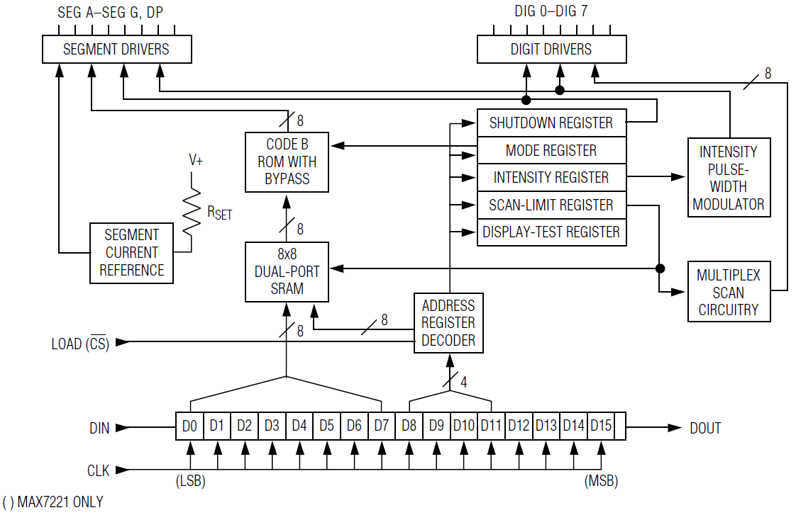
Functional Diagram of the MAX7219
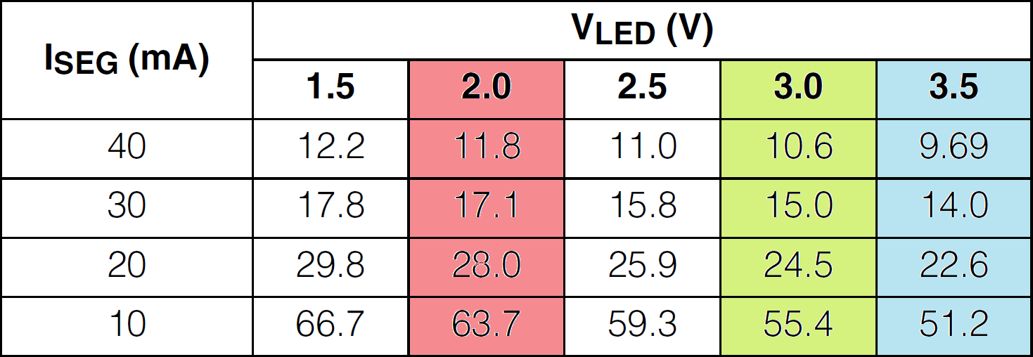
Current vs. R1 value (in kΩ). A 15 kΩ is suiteable for the used SC39-11SRWA
Source: Datasheet MAX7219/7221 from maxim integrated™.
We use the MAX7219 library from tronixstuff.com. The sketches here are based on this library as well as their examples. We also use the library from the Keypad Library for Arduino website.
Functional Diagram of the MAX7219
Current vs. R1 value (in kΩ). A 15 kΩ is suiteable for the used SC39-11SRWA
Source: Datasheet MAX7219/7221 from maxim integrated™.
We use the MAX7219 library from tronixstuff.com. The sketches here are based on this library as well as their examples. We also use the library from the Keypad Library for Arduino website.

")
✈ Arduino Sketch - Test Code
This is just a collection of testroutines to see if the scanning of the keyboard and the displaying with the MAX7219 do work correctly.
The full functionning calculator is an exercise and therefore no solution here. If you manage to convince us of beeing
an honorable teacher / instructor, we mayst consider giving away the complete sketch. (NOT YET AVAILABLE)
Sketch #1 - Displaytest
/*
 *    ARDUINO CALCDUINO SHIELD
 *    TEST OF THE DISPLAY, MAX7219
 *	  USES LIBRARY FROM HERE : http://tronixstuff.com
 *    https://www.changpuak.ch/electronics/Arduino-CALCDUINO.php
 *    Software Version 1.0, sketch_jan11a
 *    05.01.2016, Alexander C. Frank
 */

#include "LedControl.h"

int CLOCK = 13;
int DATA = 11;
int LOAD = 12;
int UNITS = 1;

LedControl lc=LedControl(DATA,CLOCK,LOAD,UNITS);

void setup()
{
	// the zero refers to the MAX7219 number, it is zero for 1 chip
	lc.shutdown(0,false);	// turn off power saving, enables display
	lc.setIntensity(0,8);	// sets brightness (0~15 possible values)
	lc.clearDisplay(0);		// clear screen
	// void LedControl::setChar(int addr, int digit, char value, boolean dp)
}

void loop()
{

	for (int pos=0; pos<6; pos++){ lc.setChar(0,pos,'-',false); delay(100); }
	for (int pos=0; pos<6; pos++){ lc.setChar(0,pos,'0',false); delay(100); }
	for (int pos=0; pos<6; pos++){ lc.setChar(0,pos,'1',false); delay(100); }
	for (int pos=0; pos<6; pos++){ lc.setChar(0,pos,'2',false); delay(100); }
	for (int pos=0; pos<6; pos++){ lc.setChar(0,pos,'3',false); delay(100); }
	for (int pos=0; pos<6; pos++){ lc.setChar(0,pos,'4',false); delay(100); }
	for (int pos=0; pos<6; pos++){ lc.setChar(0,pos,'5',false); delay(100); }
	for (int pos=0; pos<6; pos++){ lc.setChar(0,pos,'6',false); delay(100); }
	for (int pos=0; pos<6; pos++){ lc.setChar(0,pos,'7',false); delay(100); }
	for (int pos=0; pos<6; pos++){ lc.setChar(0,pos,'8',false); delay(100); }
	for (int pos=0; pos<6; pos++){ lc.setChar(0,pos,'9',false); delay(100); }

}
Sketch #2 - Keypadtest
If the Displaytest passed, you may now check the keypad scanning routine. The symbol of the
key pressed is send to the serial terminal ...
/*
 *    ARDUINO CALCDUINO SHIELD
 *    TEST OF THE KEYBOARD
 *    SOURCE : http://playground.arduino.cc/Main/KeypadTutorial
 *    https://www.changpuak.ch/electronics/Arduino-CALCDUINO.php
 *    Software Version 1.0, sketch_jan11b
 *    11.01.2016, Alexander C. Frank
 */

#include <Keypad.h>

const byte ROWS = 4; // Four rows
const byte COLS = 4; // Four columns
// Define the Keymap
char keys[ROWS][COLS] =
{
  {':','*','+','-'},
  {'4','3','8','9'},
  {'2','1','6','7'},
  {'5','0',',','='}
};
// Connect keypad ROW0, ROW1, ROW2 and ROW3 to these Arduino pins.
byte rowPins[ROWS] = { 2, 3, 4, 5 };
// Connect keypad COL0, COL1, COL2 and COL3 to these Arduino pins.
byte colPins[COLS] = { 7, 8, 9, 10 };

// Create the Keypad
Keypad kpd = Keypad( makeKeymap(keys), rowPins, colPins, ROWS, COLS );

void setup()
{
  Serial.begin(9600);
}

void loop()
{
  char key = kpd.getKey();
  if(key)  // Check for a valid key.
  {
  Serial.println(key);
  }
}
✈ Share your thoughts
The webmaster does not read these comments regularely. Urgent questions should be send via email.
Ads or links to completely uncorrelated things will be removed.
Your Browser says that you allow tracking. Mayst we suggest that you check that DNT thing ?
|
t1 = 6496 d
t2 = 269 ms |
★ ★ ★ Copyright © 2006 - 2024 by changpuak.ch ★ ★ ★
|

|