 ช้างเผือก
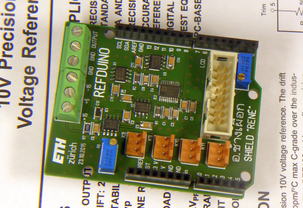
Categories
Statistics
Since 08.08.2014
Counts only, if "DNT = disabled".
Your IP is 3.135.190.101
ec2-3-135-190-101.us-east-2.
Counts only, if "DNT = disabled".
Your IP is 3.135.190.101
ec2-3-135-190-101.us-east-2.
Info

เราจะทำแบบวิศวกรผู้ยิ่งใหญ่

25. April 2024
Your valuable opinion :
April 2024 ∴ P'Bird - รูปที่มีทุกบ้าน
Arduino-Shield-RENE.php 17014 Bytes 15-02-2024 16:54:08
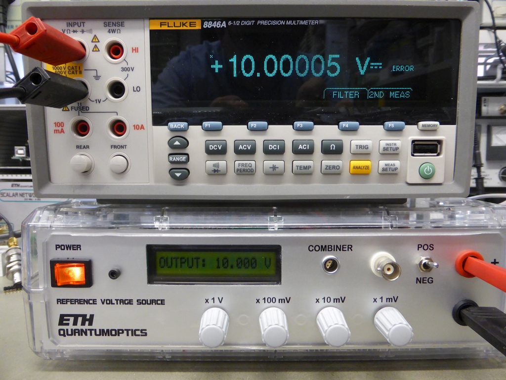
Arduino® Reference Voltage Source : REFDUINO
Shield "RENÉ"
This project is a Hack-together of an Arduino UNO (others may need modifications) and a Shield "RENÉ". It generates an ultra-stable
Reference Voltage of ± 0.001 up to ± 10.000 V, adjusteable in
0.001 V steps.
✈ Circuit Description
The device consists mainly of an REF102, a 10V reference voltage source with a 2.5ppm/°C temperature drift. It mayst be calibrated by a potentiometer
R6. This reference is fed into an AD5791 DAC (20 Bit, B version) which has an 1 ppm resolution and a 1 ppm INL. A buffer at the output shall eliminate pulling/pushing
effects of the load. We know that this DAC is expensive, but you get what you pay for. And for a reference, only the best components shall be used.
✈ Downloads


✈ Arduino Sketch - The Code
Double click on code to select ...
/*
 *    REFERENCE VOLTAGE SOURCE
 *    https://www.changpuak.ch/electronics/Arduino-Shield-RENE.php
 *    Software Version 1.4, suiteable for AD5791
 *    28.10.2015, Alexander C. Frank
 */

#include <LiquidCrystal.h>

LiquidCrystal lcd(7,6,5,4,3,2);


// INPUT
int PotiA = A0 ;        // MSB
int PotiB = A1 ;
int PotiC = A2 ;
int PotiD = A3 ;        // LSB

// OUTPUT
int SYNC = 13 ;
int SCLK = 12 ;
int SDIN = 11 ;
int SDO = 10 ;
int CLR = 9 ;
int LDAC = 8 ;

int ActualValuePoti[] = { 0, 0, 0 , 0} ;
int LastValuePoti[] = { 1, 1, 1, 1} ;
bool change = true ;      // HAS THE VOLTAGE CHANGED ???
bool first = true ;
unsigned long Spannung ;
unsigned long Zeiger ;
float LCDSpannung ;

void UpdateOutput()
{
  Zeiger = 0b00000000100000000000000000000000 ;
  if (first == false) { Spannung |= 0b000100000000000000000000 ; }

  digitalWrite(SYNC, LOW);                      // START THE WRITE CYCLE
  for (int i=0; i<24; i++)
  {
    if ((Spannung & Zeiger)>0) { digitalWrite(SDIN, HIGH); }
      else { digitalWrite(SDIN, LOW); }
    delay(1);
    digitalWrite(SCLK, HIGH); delay(1); digitalWrite(SCLK, LOW);
    Zeiger = Zeiger >> 1 ;
    delay(1);
  }
  digitalWrite(SYNC, HIGH);  delay(1);
}

void setup()
{
  pinMode(SYNC, OUTPUT);
  pinMode(SCLK, OUTPUT);
  pinMode(SDIN, OUTPUT);
  pinMode(SDO, INPUT_PULLUP);
  pinMode(CLR, OUTPUT);
  pinMode(LDAC, OUTPUT);
  lcd.begin(8, 2);
  lcd.clear();
  lcd.setCursor(0,0); lcd.print("WARMING ");
  lcd.setCursor(0,1); lcd.print("UP ...");
  digitalWrite(CLR, HIGH);
  // When tied permanently low, output is updated on the rising SYNC.
  digitalWrite(LDAC, LOW);
  delay(2000);

  // WRITE THE CONTROL REGISTER
  Spannung = 0b001000000000000000010000 ;
  UpdateOutput();
  first = false ;
  delay(2000);
}

void loop()
{

  // ---------------------------------------------------------
  LastValuePoti[3] = ActualValuePoti[3];
  ActualValuePoti[3] = analogRead(PotiD) / 113 ;
  if (ActualValuePoti[3] != LastValuePoti[3]) change = true ;
  // ---------------------------------------------------------
  LastValuePoti[2] = ActualValuePoti[2];
  ActualValuePoti[2] = analogRead(PotiC) / 113 ;
  if (ActualValuePoti[2] != LastValuePoti[2]) change = true ;
  // ---------------------------------------------------------
  LastValuePoti[1] = ActualValuePoti[1];
  ActualValuePoti[1] = analogRead(PotiB) / 113 ;
  if (ActualValuePoti[1] != LastValuePoti[1]) change = true ;
  // ---------------------------------------------------------
  LastValuePoti[0] = ActualValuePoti[0];
  ActualValuePoti[0] = analogRead(PotiA) / 102 ;
  // SPECIAL CASE 10.000 V
  if (ActualValuePoti[0] == 10)
  {
    ActualValuePoti[1] = 0 ;
    ActualValuePoti[2] = 0 ;
    ActualValuePoti[3] = 0 ;
  }
  if (ActualValuePoti[0] != LastValuePoti[0]) change = true ;

  // -------------------------------------------------------

  if ( change == true )
  {
  // UPDATE LCD
  lcd.clear();
  lcd.setCursor(0,0); lcd.print("OUTPUT: ");
  lcd.setCursor(0,1);
  LCDSpannung = (float)ActualValuePoti[0]
	  + (float)ActualValuePoti[1] * 0.1
	  + (float)ActualValuePoti[2] * 0.01
	  + (float)ActualValuePoti[3] * 0.001 ;
  lcd.print(LCDSpannung,3);
  lcd.print(" V");

  // UPDATE DAC
  // Vout = 10V * Spannung / 1'048'575
  Spannung = LCDSpannung * 104857.5 ;
  UpdateOutput();
  change = false ;
  }

  delay(321);
}
✈ How not to do it - failed approach :-(
The first approach used four DACs (MCP4725) which have been buffered. They where summed up with an resistive adder.
Mathematically, this works beautiful, but the DACs had such a huge nonlinear behavior, that a large look-up table would
have been necessary (10k entries) to make this thing work.
The Javascript below lets you "experience" how the Voltage Summer Circuit works. You may also want to have a look at www.allaboutcircuits.com.
The Javascript below lets you "experience" how the Voltage Summer Circuit works. You may also want to have a look at www.allaboutcircuits.com.
✈ How to improve it - Use multiple REF102
It is a well known trick to use multiple transistors in parallel to reduce the noise. This approach may also be used here.
The noise of the REF102 mayst be reduced by using multiple devices. In that case the outputs have to be summed up with a
resistive network. Using two devices reduces the noise by 3 dB, four devices by 6 dB and so on ...
✈ Share your thoughts
The webmaster does not read these comments regularely. Urgent questions should be send via email.
Ads or links to completely uncorrelated things will be removed.
Your Browser says that you allow tracking. Mayst we suggest that you check that DNT thing ?
|
t1 = 6496 d
t2 = 169 ms |
★ ★ ★ Copyright © 2006 - 2024 by changpuak.ch ★ ★ ★
|

|