 ช้างเผือก
Categories
Statistics
Since 08.08.2014
Counts only, if "DNT = disabled".
Your IP is 3.144.189.177
ec2-3-144-189-177.us-east-2.
Counts only, if "DNT = disabled".
Your IP is 3.144.189.177
ec2-3-144-189-177.us-east-2.
Info

เราจะทำแบบวิศวกรผู้ยิ่งใหญ่

19. April 2024
Your valuable opinion :
Arduino-Shield-TANACHAI.php 24352 Bytes 18-04-2024 00:46:03
Arduino/Genuino Transistor Curve Tracer
Shield "TANACHAI"
This is a somehow easier to reproduce version of the Curve Tracer Project.
It has the form-factor of an Arduino UNO (Leonardo), using very standard components. And yes, I saw that there are
already similiar projects out there in the endless universe web, but they are all limited to 5V. What finally came out is a (THT) soldering
exercise, a programming exercise and a course on transistor / amplifier components / circuits. Suiteable to fill one year of teaching electronics :-)
The plan was to design a very universal shield which does not rely on smd parts, so every homebrewer is able to build it. As the availablity of
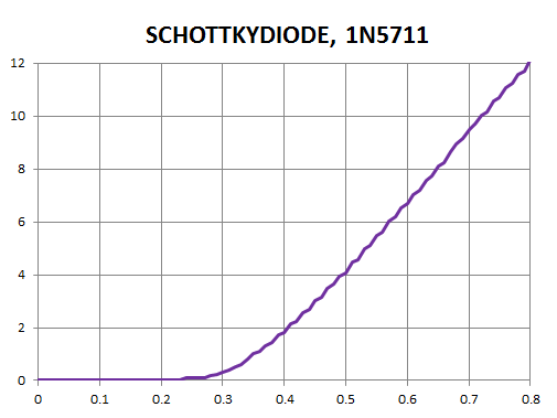
dual dac in a dil-8 case is getting smaller and smaller, we used the MCP4822 E/P which has (only) 12 bit resolution. If you zoom in (as for e.g.
diodes)
a lot - the steps of 6.6 mV become clearly visible. Some 'smooth = True' mayst be necessary ... Also necessary is, that the user knows
what he(she) is doing, as the voltages are not measured, but set. If the load is large enough, this is no problem -
just to mention the limitations right at the beginning :-)
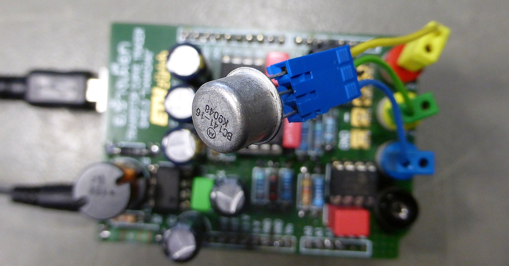
✈ The "Shield"
The shield houses all the components necessary for this project. A DC/DC converter built around a MC34063A generates a voltage of approx. 30 V.
It is designed to deliver a current of max. 150 mA. Two 8/10/12 bit DAC's are used (together with a rail to rail opamp, AD822) to produce a voltage
from 0 V to 27.0336 V. Whilst the Gate/Base drive is directly powered by the opamp, an additional transistor forms something like a "power stage"
which shall handle currents up to approx. 100 mA. In order to increase reliability, we used a heatsink for it. The current is sensed by
a 1Ω 1% resistor, amplified by a MCP6271 (48x) and finally read by the analog port of the UNO. The shield is capable to be controlled
by a computer via the usb port. An external power supply 12 V / 1 A is necessary.
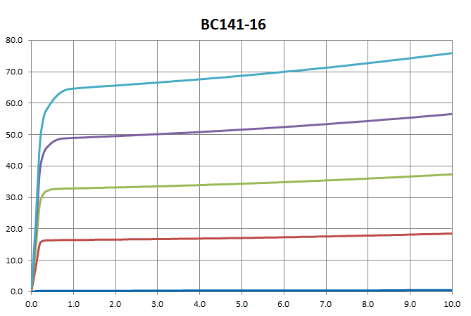
In order not to "forget" one type, we hacked together an overview. Some more commonly used types are measured in detail - to verify the functionality and correctness of this thing. The numbers in the field "connections" refer to the numbers on the shield.
In order not to "forget" one type, we hacked together an overview. Some more commonly used types are measured in detail - to verify the functionality and correctness of this thing. The numbers in the field "connections" refer to the numbers on the shield.
| # | ? | TYPE | SYMBOL | CONNECTIONS | NOTE | DATASHEET |
| 1 | JFET N-CH | 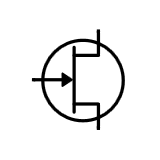 |
0: GND 1: DRAIN 2: GATE 3: SOURCE |
V2 < V3 | J309, J310 | |
| 2 | JFET P-CH | 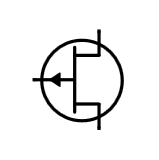 |
0: GND 1: DRAIN 2: GATE 3: SOURCE |
V2 > V3 | MMBF5460 | |
| 3 | MOSFET N-CH DEPLETION |
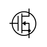 |
0: GND 1: - 2: - 3: - |
ID@UDS: + UGS: +/- RARELY USED |
CPC3980 | |
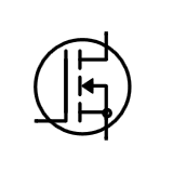
| 4 | MOSFET P-CH DEPLETION |
 |
0: GND 1: DRAIN 2: GATE 3: SOURCE |
ID@UDS: - UGS: +/- RARELY USED |
CSD25483F4 | |
| 5 | MOSFET N-CH ENHANCEMENT |
 |
0: GND 1: SOURCE 2: GATE 3: DRAIN |
ID@UDS: + UGS: + POWER AMPLIFIER |
IRF7842 | |
| 6 | MOSFET P-CH ENHANCEMENT |
 |
0: GND 1: DRAIN 2: GATE 3: SOURCE |
ID@UDS: - UGS: - POWER AMPLIFIER |
IRF7240 | |
| 7 | BIPOLAR NPN |  |
0: GND 1: EMITTER 2: BASE 3: COLLECTOR |
Ibe > 0 |
BC849 BF199 |
|
| 8 | BIPOLAR PNP | 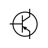 |
0: GND 1: COLLECTOR 2: BASE 3: EMITTER |
Ibe < 0 | BC859 |
And yes, two port devices can also be measured. A selection is put together here.
| # | ? | TYPE | SYMBOL | CONNECTIONS | NOTE | DATASHEET |
| 9 | DIODE SILICIUM (GERMANIUM) |
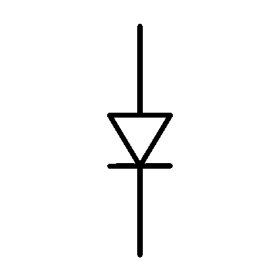 |
0: GND 1: ANODE 2: - 3: CATHODE |
V1 < V3 | 1N4148 | |
| 1 0 |
DIODE SCHOTTKY |
 |
0: GND 1: ANODE 2: - 3: CATHODE |
V1 < V3 | BAT43 | |
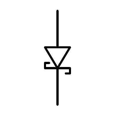
| 1 1 |
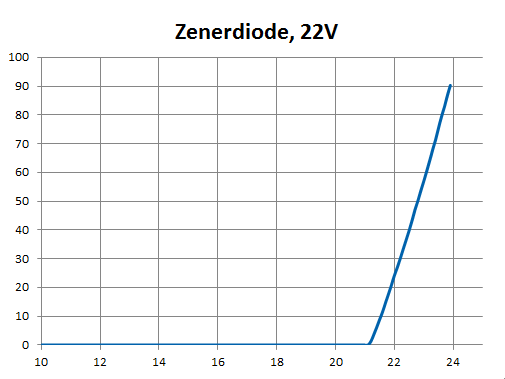
ZENER DIODE |
 |
0: GND 1: ANODE 2: - 3: CATHODE |
V1 < V3 V3 < 22V |
BZV85-C9V1 | |
| 1 2 |
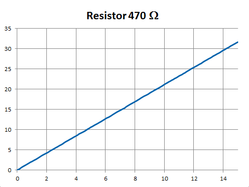
RESISTOR |  |
0: GND 1: LEAD1 2: - 3: LEAD2 |
R < 99 kΩ | MBE/SMA 0414 | |
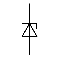
| 1 3 |
VOLTAGE DEPENDENT RESISTOR |
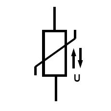 |
0: GND 1: LEAD1 2: - 3: LEAD2 |
V < 22V | SIOV-S05K11 |
✈ The Sketches #1 (Arduino and Spreadsheet)
Just as a proof, that "this thing" works.


✈ Downloads & More :-)


✈ Max from Berlin designed a case for that thing !
Max from Berlin designed a nice case for this shield. He even wants to share his work with you.
Download the zip file below his picture ...


✈ Daniel (Slovakia) elevated this Project to a new level !
Daniel spent quite some time to build this board and came up with some suggestions on how to improve this
shield. The version 2.2 is made possible by his extensive feedback. Even more, he allowed
to publish his developped c-code here. The main improvement suggested to add a Resistor of 4.3 kΩ at
the output of the step-up converter to improve stability, but we can get away with a change of component values.
New is the value of R7 = 3 kΩ and R6 = 120 Ω. This shall have a similiar effect as adding a
resistor of 4.3 kΩ.
Using a USB galvanic isolator is strongly recommended.
Using a USB galvanic isolator is strongly recommended.


✈ Share your thoughts
The webmaster does not read these comments regularely. Urgent questions should be send via email.
Ads or links to completely uncorrelated things will be removed.
Your Browser says that you allow tracking. Mayst we suggest that you check that DNT thing ?
|
t1 = 6490 d
t2 = 389 ms |
★ ★ ★ Copyright © 2006 - 2024 by changpuak.ch ★ ★ ★
|

|