 ช้างเผือก
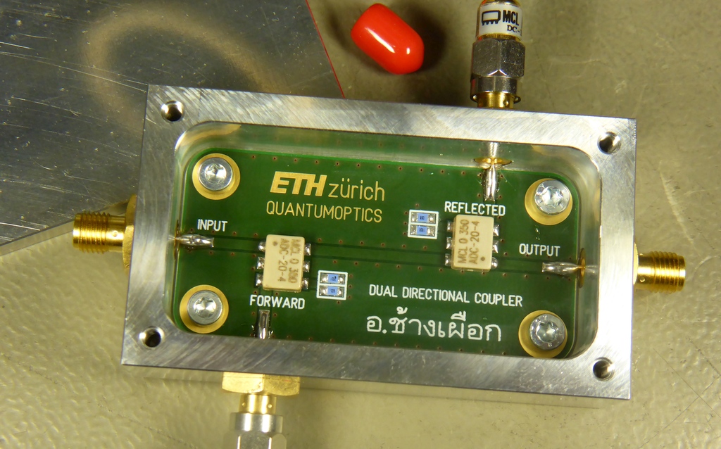
Categories
Statistics
Since 08.08.2014
Counts only, if "DNT = disabled".
Your IP is 18.219.22.169
ec2-18-219-22-169.us-east-2.
Counts only, if "DNT = disabled".
Your IP is 18.219.22.169
ec2-18-219-22-169.us-east-2.
Info

เราจะทำแบบวิศวกรผู้ยิ่งใหญ่

24. April 2024
Your valuable opinion :
April 2024 ∴ P'Bird - รูปที่มีทุกบ้าน
DIY-DualDirectionalCoupler.php 14380 Bytes 31-05-2023 09:49:15
DIY Dual Directional Coupler, 5 - 1000 MHz, 20 dB
An Add-On to our Scalar Network Analyzers
This is not a new invention. It's just a hack together of some (very) nice parts. And the result is an 'even nicer' part. (So we think :-)
✈ Hardware Description
This design uses two times an ADC-20-4 or an ADC-10-4 from Mini Circuits. A small printed circuit board was designed to offer
adequate 50 Ω traces, as it should go up to 1000 MHz. The termination is done by two resistors 0805, 100 Ω in parallel.
We used sma connectors to keep the geometry small. The case was milled from aluminium. Surface coated with nickel. As connectors,
you mayst use MC000242 (Multicomp) or 142-0701-411 (JOHNSON).


✈ Performance (2 x ADC-20-4+ assembled)
Figure 1. Coupling (INPUT - INCIDENT) or (OUTPUT - REFLECTED)
Figure 2. Main Line Loss (INPUT - OUTPUT)
Figure 3. Return Loss: Input
Figure 4. Return Loss: Output
Figure 5. Return Loss: Coupling (INCIDENT or REFLECTED)
Figure 6. Directivity
Note : The directivity is the difference in dB of the power output of the two coupled ports, when power is transmitted in a constant direction on the main-line.
All measurements done with an hp 8753 ES. We apologise for the de-pixeled graphs. As it seems, that Mini Circuits specifies very diffidently, this dual directional coupler mayst also be used slightly out of range :-)
✈ RF directional coupler 'Quick bleach'
Assuming that the rf source is connected at the input port and the load is connected at the output port,
this dual directional coupler outputs a signal at the forward port which is 20 dB lower than the power entering at the input port. Vice versa
it outputs a signal at the reflected port which is 20 dB lower than the power entering at the output port. Those 20 dB are
referred to as coupling coefficient. An essential feature of directional couplers is that they only couple power flowing in one direction.
The lower the signal at the coupled port, the more signal is available to the through line.
In case the load is not matched to the system impedance, it will reflect power. Therefore the signal at the reflected port is a measure for the impedance of the load.
It is possible to design directional couplers in various ways. Depending on the frequency, the design may use lumped elements, transmission lines or waveguides. The design here uses lumped elements (transformers). Mini Circuits ADC-10-4 or Mini Circuits ADC-20-4.
")
")
Read more on Jeff's blog.
The lower the signal at the coupled port, the more signal is available to the through line.
In case the load is not matched to the system impedance, it will reflect power. Therefore the signal at the reflected port is a measure for the impedance of the load.
It is possible to design directional couplers in various ways. Depending on the frequency, the design may use lumped elements, transmission lines or waveguides. The design here uses lumped elements (transformers). Mini Circuits ADC-10-4 or Mini Circuits ADC-20-4.
Read more on Jeff's blog.
✈ Alain explains how a Directional Coupler works
✈ Homebrew 50 Ω Terminations
When building terminations for 50 Ω, several possibilities arise. 1 x 51 Ω, 2 x 100 Ω, 3 x 150 Ω, 4 x 200 Ω, 6 x 300 Ω, [...]
In order to see, if there is a difference, we build them using an sma connector and 0603 resistors
(the set from Constructiva AG, using Vishay/Yageo 1% thick film resistors). As at very high frequencies solder/flux left-overs may have an influence,
the sma connectors have been cleaned with isopropanol. Measurements have been done with an hp 8753 ES, as calibration standard, we used a (new)
Huber & Suhner 65 SMA-50-0-36/111 NE.
It can be seen, that DIY design and assembly of 50 Ω terminations yields very useable results when considering rf design techniques. The best solution here is 2 x 100 Ω, obviously some parasistic effects add up when using more of those resistors. The Measurement below refers to the 2 x 100 Ω version.


| Configuration | S11 at 1 MHz | S11 at 1 GHz | S11 at 2 GHz | S11 at 3 GHz |
| 51 Ω | - 39.2 dB | - 26.8 dB | - 21.4 dB | - 17.0 dB |
| 2 x 100 Ω | - 60.8 dB | - 49.2 dB | - 46.2 dB | - 45.1 dB |
| 3 x 150 Ω | - 56.2 dB | - 33.8 dB | - 27.9 dB | - 26.1 dB |
| 4 x 200 Ω | - 65.7 dB | - 30.0 dB | - 25.2 dB | - 22.2 dB |
| 6 x 300 Ω | - 59.6 dB | - 25.7 dB | - 19.0 dB | - 16.4 dB |
It can be seen, that DIY design and assembly of 50 Ω terminations yields very useable results when considering rf design techniques. The best solution here is 2 x 100 Ω, obviously some parasistic effects add up when using more of those resistors. The Measurement below refers to the 2 x 100 Ω version.

✈ Please cite as :
Dipl.-Ing. Alexander C. Frank, "DIY Dual Directional Coupler, 5 - 1000 MHz, 20 dB"
https://www.changpuak.ch/electronics/DIY-DualDirectionalCoupler.php
https://www.changpuak.ch/electronics/DIY-DualDirectionalCoupler.php
✈ Share your thoughts
The webmaster does not read these comments regularely. Urgent questions should be send via email.
Ads or links to completely uncorrelated things will be removed.
Your Browser says that you allow tracking. Mayst we suggest that you check that DNT thing ?
|
t1 = 6495 d
t2 = 300 ms |
★ ★ ★ Copyright © 2006 - 2024 by changpuak.ch ★ ★ ★
|

|