 ช้างเผือก
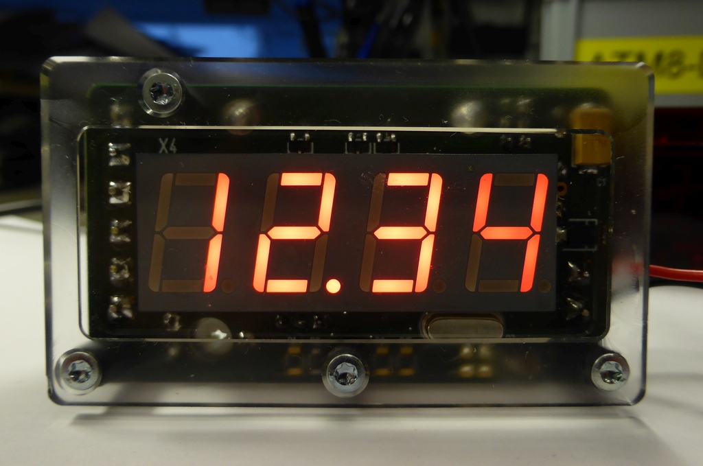
Categories
Statistics
Since 08.08.2014
Counts only, if "DNT = disabled".
Your IP is 3.134.102.182
ec2-3-134-102-182.us-east-2.
Counts only, if "DNT = disabled".
Your IP is 3.134.102.182
ec2-3-134-102-182.us-east-2.
Info

เราจะทำแบบวิศวกรผู้ยิ่งใหญ่

27. April 2024
Your valuable opinion :
LED-DigitalVoltmeterModule.php 13711 Bytes 12-02-2018 11:22:26
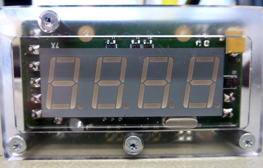
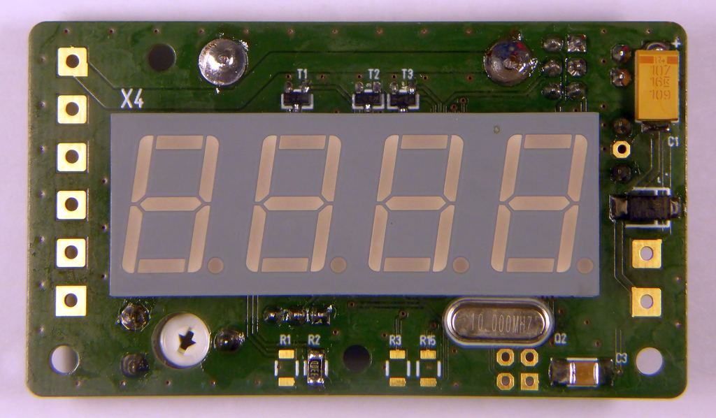
DIY 4-Digit LED Digital Voltmeter Module
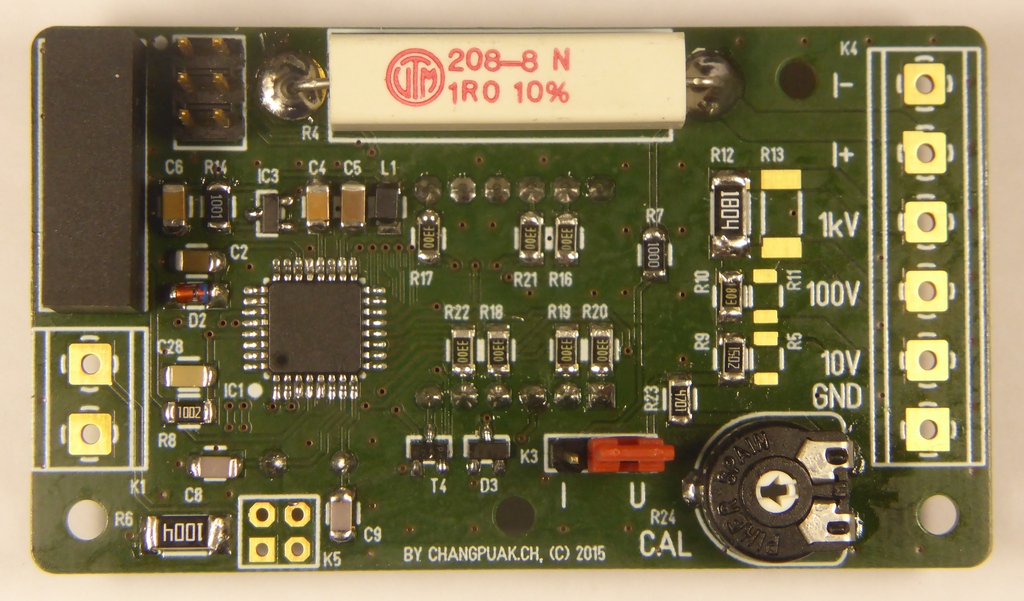
Three Voltage Ranges (DC: 1000V, 100V, 10V, AC: 700V, 70V, 7V) as well as an onboard Shunt (1Ω) allows to measure Voltages and Currents. A DC/DC Converter
offers galvanic Isolation from the Supply. An Atmega8 with a 10 bit A/D Converter as well as an onboard Precision Voltage References make this
an useful and educational utility.
")
Circuit
The circuit is straightforward. To overcome difficulties in measuring voltages not related to the own supply, a dc/dc converter takes
care of the galvanic isolation. Depending on the supply, a lot of different models can be used. We tested TMR 1-1211, TMA 0505S and
TMH 1205S, all from Traco Power. The output is always 5 V. With this supply, we power (of course, all the circuit) but also our
voltage reference. An LM4040 is used here. It delivers a reference voltage of + 2.5 V. This also allows for overvoltage detection.
The used 7-Segment Display will then display "HELP". It is a ELF-511SURWA or SYGWA (green or red). This was chosen because
it has the lowest pin-count. (The blue version ELF-511UBWA seems to be harder to get ...)
The voltage divider shall scale down the input to a maximum equal to the reference voltage. It can be changed easily as a lot of variations from the same reference exist. (e.g. 1.225 V, 2.500 V, 3.000 V, 3.300 V, 4.096 V). As the input resistance of the Atmega mayst vary, we introduced a potentiometer for adjustement. The current measurement shunt is very low in resistance, so an adjustement was omitted. When measuring currents, the full scale voltage drop of 2.5 V mayst become a problem, especially in low voltage applications.
Both inputs are protected by a zenerdiode (ZPD4.7V) against overvoltage and a schottkydiode (BAT41) against wrong polarity. A large capacitor (10 µF) shall keep the voltage at the input stable. (A/D converters switch capacitances at the input, so a low impedance is mandatory).
A lot of settings are done in the firmware. This makes sure, that the panelmeter works correct right from the first power-up, but encourages also advanced students to spend some time with software developping.
Measure DC Voltage
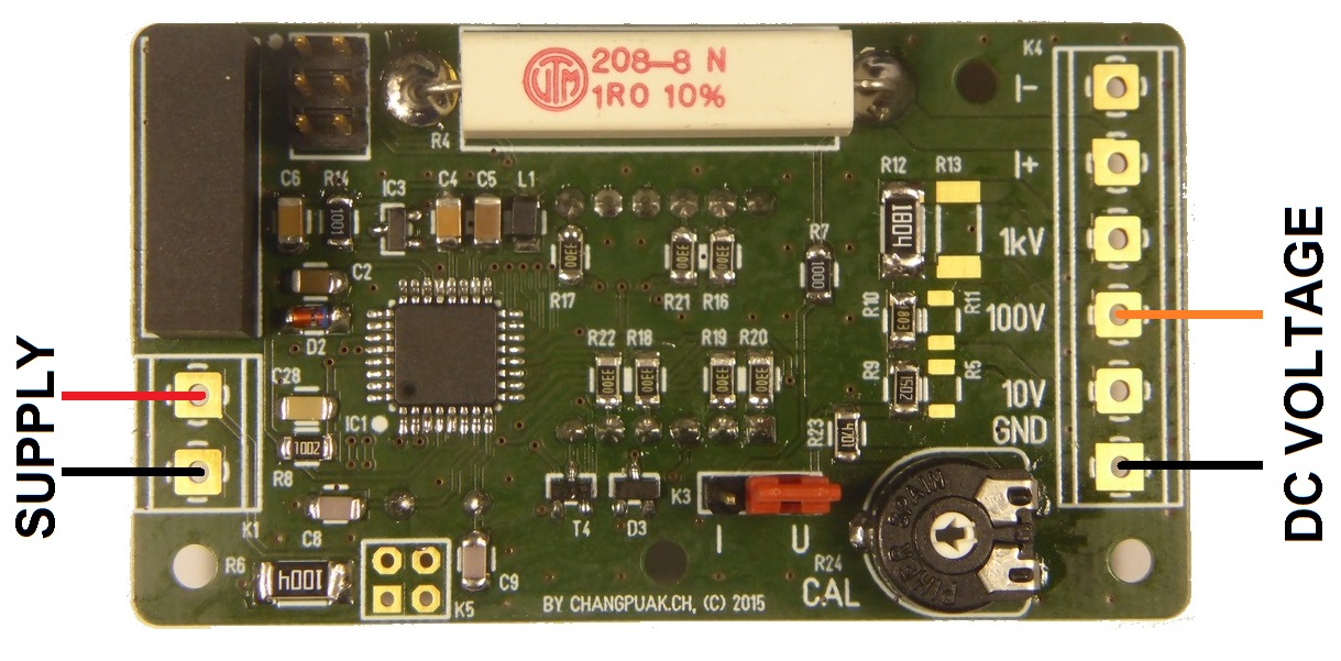
To measure a dc voltage, you just have to connect the negative terminal to "GND" and the positive terminal to the appropriate voltage like "100 V" to measure voltages up to 100 V. The decimal point is set with a resistor (R1, R2, R3, R15). The correction factor (in the firmware) is set to 1. The Jumper has to be set to "U".
Measure AC Voltage
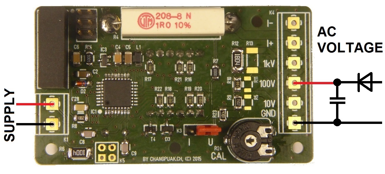
To measure an ac voltage, you need to add a diode for rectification and a capacitor for smoothing. Connect the diode (Cathode) and the positive side of the capacitor at the + 100 V terminal (or any other) and the negative side of the capacitor together with the - to GND. We now measure the peak value of the voltage. When measuring sinusoidal voltages, this is sqrt(2) times larger. In order to measure the effective voltage, the voltage divider mayst be changed to compensate that. As a second option, the correction factor (in the firmware) may be set to 0.707106. An additional error may be caused by the voltage drop of the rectifier. Keep it small by using schottky diodes. The 1000 V range may then only be used up to 650 V ac. When measuring 50 Hz, a 10 µF Cap should be o.k. The decimal point is set with a resistor (R1, R2, R3, R15). The Jumper has to be set to "U".
Measure DC Current
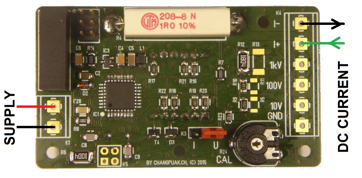
To measure a dc current, you just have to connect the negative terminal to "I-" and the positive terminal to "I+". For larger currents, other shunt resistors like 0.1 Ω are to be considered. For the case of 1 Ω Shunt, the correction factor shall be set to 0.25 (in the firmware). The GND of the panelmeter is connected to the "I-", so the task is to measure a voltage with respect to GND. The Jumper has to be set to "I".
Measure AC Current

To measure an ac current, add a bridge rectifier. This makes sure, that the current through the shunt flows only in one direction. The decimal point is set with a resistor (R1, R2, R3, R15). The correction factor (in the firmware) is set to 0.25. The Jumper has to be set to "I".
Use as a Thermometer

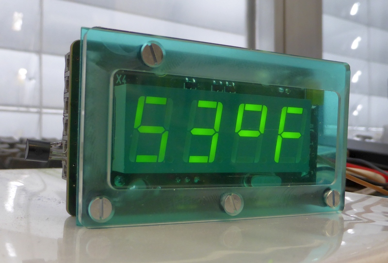

This Panelmeter can easily be repurposed into a thermometer. All you need is a LM35 or similiar device. Connect it to the 10 V Range. As it's output voltage is usually small, R5 or R9 may be bypassed with a 0 Ω resistor. The + 5 V supply may be taken from the ISP header. The firmware must be informed of the new use by setting is_a_thermometer = 1; which is zero in all other applications. Luckily the character "F" may also be displayed (on the 7-Segment Display), so degrees Fahrenheit are also possible. Hint for firmware : °F = °C x 9/5 + 32. Hint for hardware : you mayst want to use the lowest possible reference voltage.
Downloads


This project was designed for our trainees as an smd soldering excercise.
✈ Share your thoughts
The webmaster does not read these comments regularely. Urgent questions should be send via email.
Ads or links to completely uncorrelated things will be removed.
Your Browser says that you allow tracking. Mayst we suggest that you check that DNT thing ?
|
t1 = 6498 d
t2 = 181 ms |
★ ★ ★ Copyright © 2006 - 2024 by changpuak.ch ★ ★ ★
|

|