 ช้างเผือก
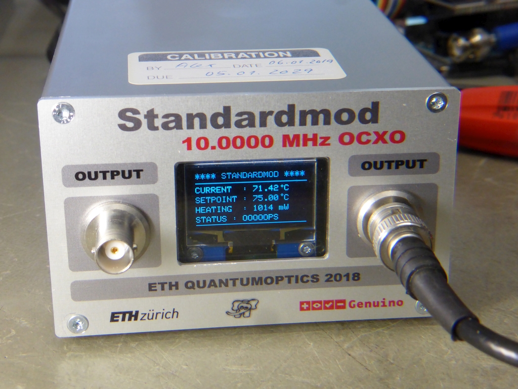
Categories
Statistics
Since 08.08.2014
Counts only, if "DNT = disabled".
216.73.216.253
216.73.216.253
Counts only, if "DNT = disabled".
216.73.216.253
216.73.216.253
Info

เราจะทำแบบวิศวกรผู้ยิ่งใหญ่

27. July 2026
YOUR OPINION •••
average: 0.001, n: 0

When using this form, your ip is stored in order to avoid multiple voting on the same website. That's it.
When using this form, your ip is stored in order to avoid multiple voting on the same website. That's it.
เราจะทำแบบวิศวกรผู้ยิ่งใหญ่
Arduino-Shield-STANDARDMOD.php 20108 Bytes 04-03-2025 19:11:03
Arduino/Genuino STANDARDMOD
An instructive 10 MHz OCXO Shield
This is a shield to measure the Frequency-Temperature Characteristics of a Quartz Crystal. When done, you choose
an operating point. The crystal is heated to a desired Temperature. The Output Frequency can then be
fine-adjusted by a DDS (AD9835) in steps of 1 Hz. (when using the Arduino library from GitHub). Almost any
Reference Frequency is possible !
✈ The used Quartz Crystal
Is a XA 983 from KVG. It is cut therefore, that it has a very low frequency drift at 75 ° Celsius.
Here are the detailed specifications :
Here are the detailed specifications :
| Specification of a Quartz Crystal Unit | XA 983 from KVG |
| Cut : | AT |
| Package : | HC-43/U |
| Frequency : | 10.000000 MHz |
| Mode of vibration : | fundamental |
| Temperature range 1 : | 65.0 °C to 85.0 °C |
| Frequency stability vs. temperature 1 : | max ± 0.5 ppm |
| Reference temperature : | 75.0 °C |
| Adjustment tolerance at 75.0 °C : | max ± 10.0 ppm |
| Load capacity CL : | 30 pF |
| Equivalent parameters C0 : | max 3.00 pF |
| Equivalent series resistance R1 : | from 0 to 10 Ohms |
| Aging @ 75.0 °C : | max ± 1.00 ppm / year |
| Level of drive : | 0.01 mW |
| Spurious modes : | Rs/R1 > 5.0 from Fo to Fo+200 kHz |
| Operating temperature range : | 65 °C to 85 °C |
✈ Circuit Description
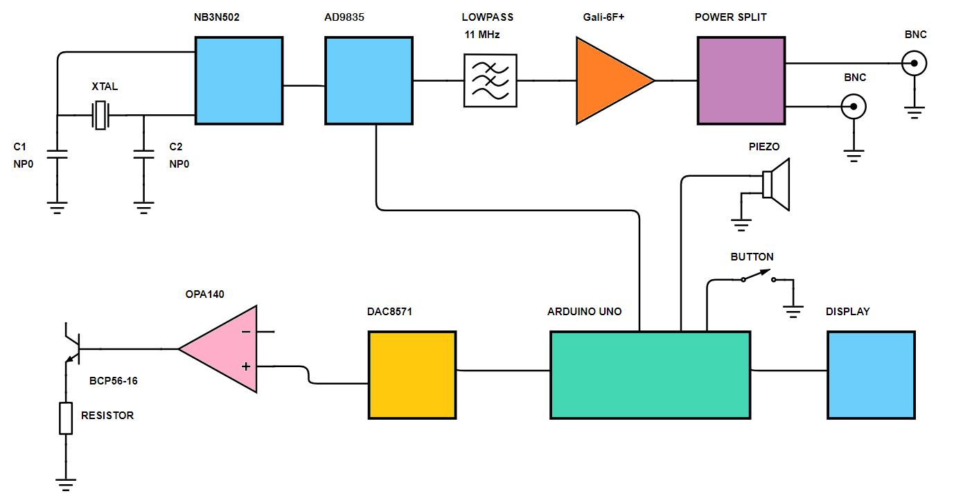
This shield consists of a Crystal Oscillator (NB3N502, with multiplier), a Heating Circuit and a DDS (AD9835)
for fine adjustement of the frequency.
You can use any frequency in the range of 5 ... 27 MHz.
The Oscillator outputs
a Frequency of 2, 2.5, 3, 3.33, 4, 5 times the Crystal Frequency. (14 MHz to 190 MHz). This Frequency is used to clock the DDS (max. 50 MHz).
The DDS has a 32-Bit Frequency Tuning Word. This means, that you can adjust the frequency to one part in 4 billion.
The TMP101 is used to monitor the Crystal temperature. The output of the DDS
is lowpass-filtered (11 MHz, here) and then amplified by a Gali-6F+ (12 dB Gain at 50 mA). A power splitter (ADP-2-1+) from Mini Circuits finally
generates two output signals which have an isolation > 30 dB at 10 MHz. The Arduino can switch on/off a piezo beeper to indicate, if the temperature
is off.


✈ The Oscillator • NB3N502 from ON Semiconductor
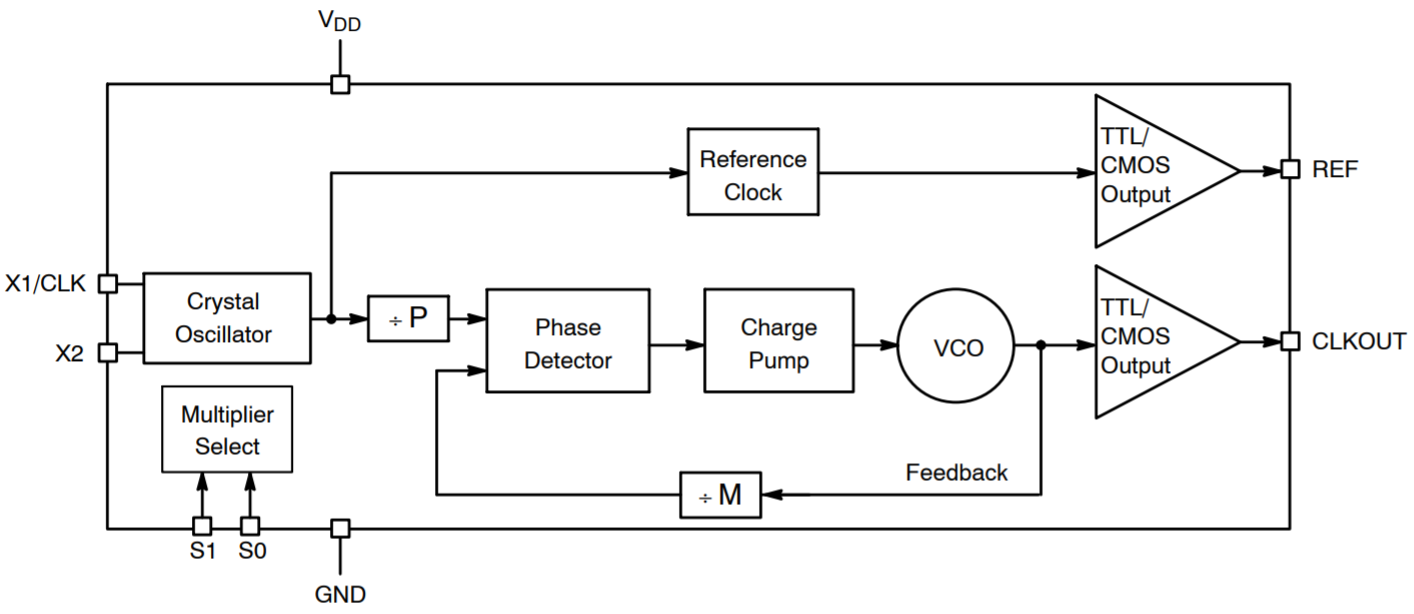
NB3N502 Block Diagram, Drawing courtesy of ON Semiconductor
This Oscillator was chosen, because it is a useful device and yes, because it was in our treasure-box. It allows the easy generation of almost any carrier without any programming. We did some investigation earlier on this circuit here.
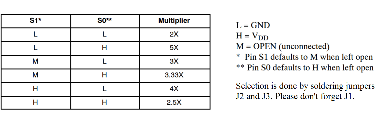
"The NB3N502 is a clock multiplier device that generates a low jitter, TTL/CMOS level output clock which is a precise multiple of the external input reference clock signal source. You can use any crystal in the range of 5 − 27 MHz". The PLL can easily be configured by just two pins. The table below shows the clock multiplying settings. And yes, for an OCXO you should use only NP0 Capacitors.
✈ Stability • Accuracy • Long Term Stability • Allan Deviation
The design is based on a circuit designed by my colleague, Dipl. Ing. Peter Märki.
You mayst find details on the heating circuit on the NCCR "QSIT - Quantum Science and Technology" website.
What is this Ageing stuff anyhow ?
In terms of electronic circuits, this means that one or more parameters change slowly with age. For a crystal oscillator, this means, that the frequency changes with time when external factors to the oscillator such as environment and power supply are kept constant. Ususally the frequency will rise.
What is this Allan Deviation ?
This is the standard method of characterizing the frequency stability of oscillators in the time domain, both short and long term. The following test-setup was used. Results to be seen in the "Performance" section.
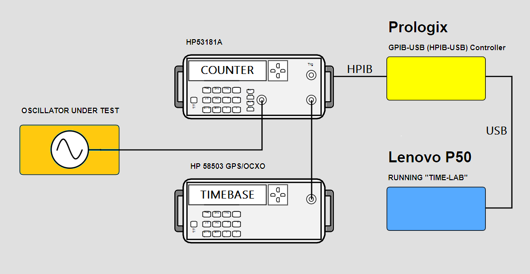
If you want to set up such a test-bench, choose a counter with a small resolution. See the influence here. Target is in the 1... 10 Picosecond range. The lower, the b€tter :-)
What is this Ageing stuff anyhow ?
In terms of electronic circuits, this means that one or more parameters change slowly with age. For a crystal oscillator, this means, that the frequency changes with time when external factors to the oscillator such as environment and power supply are kept constant. Ususally the frequency will rise.
What is this Allan Deviation ?
This is the standard method of characterizing the frequency stability of oscillators in the time domain, both short and long term. The following test-setup was used. Results to be seen in the "Performance" section.
If you want to set up such a test-bench, choose a counter with a small resolution. See the influence here. Target is in the 1... 10 Picosecond range. The lower, the b€tter :-)
✈ Test Sketch for Arduino/Genuino UNO
Double click on code to select ...
/* /////////////////////////////////////////////////////////////////////
ARDUINO/Genuino (MEGA2560) Sketch for "OCXO 10 MHz"
https://www.changpuak.ch/electronics/Arduino-Shield-STANDARDMOD.php
Software Version 1.9,
23.07.2019, Alexander Sse Frank,
//////////////////////////////////////////////////////////////////////*/

#include <Wire.h>
#include <Adafruit_GFX.h>
#include <Adafruit_SH1106.h>
#include "AD9835.h"

AD9835 dds(
        3, // FSYNC
        5, // SCLK
        4, // SDATA
        2, // FSEL, NO HAVE
        A2, // PSEL1, NO HAVE
        A1, // PSEL0, NO HAVE
        40000000 // MasterClockFrequency
    );

float SetPointTemp = 75.0 ;         // TEMPERATURE
unsigned int SetPointDAC = 48510  ; // INTEGER
float CurrentTemp = 0.0 ;

float HeatPower = 0.0 ;
float HeatPowerVolt = 0.0 ;
boolean Reliable = false ;

int BEEPER = A2 ;
int BUTTON = A3 ;
int HeatPowerPin = A0 ;
int TMP101 = 0x4A ;

int DAC8571 = 0x4C ;

unsigned long XTAL = 10000000 ;   // THE QUARTZ IN USE
unsigned long NB3N502_MULTI = 4 ; // AS SELECTED BY J2 (S1) AND J3 (S0)
unsigned long DDS_CLOCK = NB3N502_MULTI * XTAL ;  // 40 MHz
unsigned long FREQ = 9997428 ;    // DESIRED REFERENCE CLOCK
unsigned long REF_MUL = 0x0000 ;  // WE DON'T USE THIS


// OLED 128x64 with SH1106 Controller
// E.G. DM-OLED13-625
#define OLED_MOSI  9
#define OLED_CLK   8
#define OLED_DC    11
#define OLED_CS    12
#define OLED_RESET 10
Adafruit_SH1106 display(OLED_MOSI, OLED_CLK, OLED_DC, OLED_RESET, OLED_CS);

#if (SH1106_LCDHEIGHT != 64)
#error("Height incorrect, please fix Adafruit_SH1106.h!");
#endif


void setup()
{
  delay(999);
  pinMode(BEEPER, OUTPUT);
  digitalWrite(BEEPER, LOW);
  pinMode(BUTTON, INPUT_PULLUP);

  // DEFINE INPUT
  pinMode (HeatPowerPin, INPUT_PULLUP);
  // INIT OLED
  display.begin(SH1106_SWITCHCAPVCC);
  // SHOW STARTUP SCREEN
  display.clearDisplay();
  display.drawLine(0, 14, 128, 14, WHITE);
  display.setTextSize(1);
  display.setTextColor(WHITE);
  display.setCursor(0,0);
  display.println("**** STANDARDMOD ****");
  display.setTextSize(1);
  display.setCursor(0,21);
  display.println("A 10 MHz OCXO");
  display.setCursor(0,33);
  display.println("BASED ON THE AD9835");
  display.setCursor(0,45);
  display.println("(C) ETH QUANTUMOPTICS");
  display.setCursor(0,57);
  display.println("BUILT 24.07.2019");
  display.display();

  delay(9999);

  // POST #1 -----------------------------------------------------------
  digitalWrite(BEEPER, HIGH);
  delay(1999);
  digitalWrite(BEEPER, LOW);
  // -------------------------------------------------------------------
  Wire.begin();        // I2C
  Serial.begin(9600);  // SERIAL
  // INIT TMP101 - SET RESOLUTION TO 12 Bits
  Wire.beginTransmission(TMP101);
  Wire.write(0x01);    // Configuration Register
  Wire.write(0x60);    // R0 and R1 = 1
  Wire.endTransmission();

  UpdateDAC();

  dds.begin();
  dds.setFrequencyHz(0, FREQ);
  dds.selectFrequencyRegister(0);
  dds.enable();
}


void UpdateDAC()
{
  unsigned long msb = (SetPointDAC & 0xFF00) >> 8 ;
  unsigned long lsb = SetPointDAC & 0xFF ;
  Wire.beginTransmission(DAC8571);
  // CONTROL BYTE
  // Write temporary register and load
  // DAC with data
  Wire.write(0x10);
  // MSB
  Wire.write(msb);
  // LSB
  Wire.write(lsb);
  Wire.endTransmission();
}

void UpdateHeatPower()
{
  // VOLTAGE
  HeatPowerVolt = map(analogRead(HeatPowerPin),0,1023,0.0,19.9);
  HeatPower = HeatPowerVolt * HeatPowerVolt / 0.16666666666666  ;
}

void UpdateCurrentTemp()
{
  Wire.beginTransmission(TMP101);
  Wire.write(0x00);
  Wire.endTransmission();
  Wire.requestFrom(TMP101,2);
  int temp_hi = Wire.read();
  int temp_lo = Wire.read();
  int temp = (( temp_hi << 8 ) | temp_lo ) >> 4 ;
  CurrentTemp = (CurrentTemp + temp * 0.0625) / 2.0 ;
}


void UpdateOLED()
{
  display.clearDisplay();
  display.drawLine(0, 12, 128, 12, WHITE);
  display.setTextSize(1);
  display.setTextColor(WHITE);
  display.setCursor(0,0);
  display.println("**** STANDARDMOD ****");
  display.setTextSize(1);
  display.setCursor(0,17);
  display.print("CURRENT  : ");display.print(CurrentTemp,2);
  display.println(" C");
  display.drawCircle(99, 18, 1, WHITE);
  display.setCursor(0,29);
  display.print("SETPOINT : 75.00");
  display.println(" C");
  display.drawCircle(99, 29, 1, WHITE);
  // display.println(" V");
  display.setCursor(0,41);
  display.print("HEATING  : ");display.print(HeatPower,0);
  display.println(" mW ");
  display.setCursor(0,53);
  display.print("STATUS : ");
  if (abs(CurrentTemp-75.0) < 0.6) display.print("RELIABLE");
  else display.print("OUT OF SPEC");
  delay(100);
  digitalWrite(BEEPER, LOW);
  display.drawLine(0, 63, 128, 63, WHITE);
  display.display();
}


// /////////////////////////////////////////////////////////////


void loop()
{
  UpdateCurrentTemp() ;
  UpdateHeatPower() ;
  UpdateOLED() ;
  Serial.println(CurrentTemp,3);
  delay(999) ;
}


// /////////////////////////////////////////////////////////////
// END OF FILE.
// /////////////////////////////////////////////////////////////
✈ Performance
The performance was measured with a hp53181A (clocked by a hp58503) and the software TimeLab from
Miles Design LLC. See the test-setup above ...
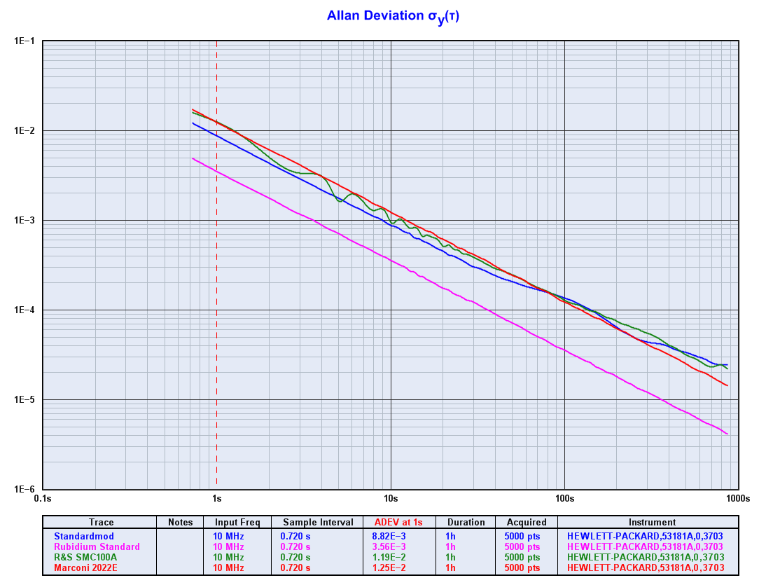
Allan Deviation of several Oscillators, measured with Time Lab
One can see, that the "Standardmod" is less precise than a Rubidium Standard but in very good society.
One can see, that the "Standardmod" is less precise than a Rubidium Standard but in very good society.
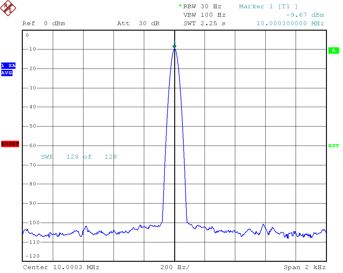
Spectral purity of the output signal (the garbage is - of course - outside this window :-)
✈ Credits • Note of Thanks
We would like to thank the staff of Kristall Verarbeitung Neckarbischofsheim (Germany) for their efforts to supply us
(our research group at ETH zürich)
with free samples and a lot of hints and advice.
ขอขอบพระคุณทุกท่าน.
ขอขอบพระคุณทุกท่าน.

The first unit will be part of a new MOT experiment in the Advanced Student Laboratory for which
my coworkers (Dr. Andrea Morales and Joaquín Minguzzi) won the ETH VP award 2019. Congratulations :-)
✈ Share your thoughts
The webmaster does not read these comments regularely. Urgent questions should be send via email.
Ads or links to completely uncorrelated things will be removed.
|
t1 = 7319 d
t2 = 269 ms |
★ ★ ★ Copyright © 2006 - 2026 by changpuak.ch ★ ★ ★
|

|