 ช้างเผือก
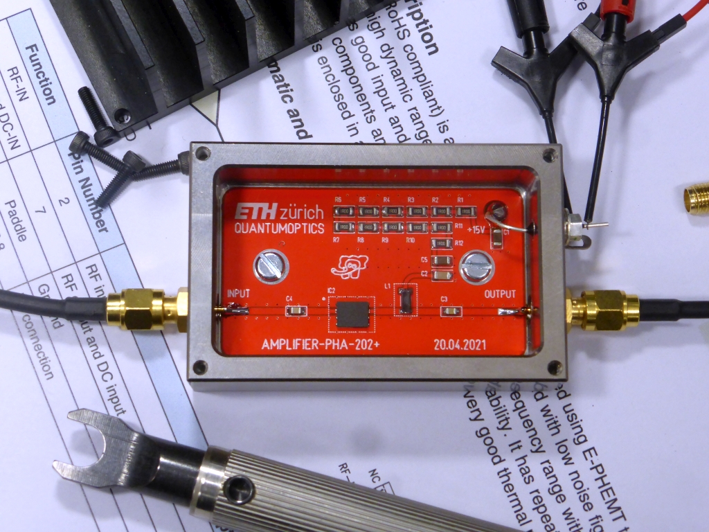
Categories
Statistics
Since 08.08.2014
Counts only, if "DNT = disabled".
216.73.216.253
216.73.216.253
Counts only, if "DNT = disabled".
216.73.216.253
216.73.216.253
Info

เราจะทำแบบวิศวกรผู้ยิ่งใหญ่

27. July 2026
YOUR OPINION •••
average: 9.000, n: 1

When using this form, your ip is stored in order to avoid multiple voting on the same website. That's it.
When using this form, your ip is stored in order to avoid multiple voting on the same website. That's it.
PHA-202+Amplifier.php 8660 Bytes 08-06-2025 10:25:10
PHA-202+ Amplifier
+30 dBm (1 Watt), 2 – 2500 MHz, Gain 17 dB
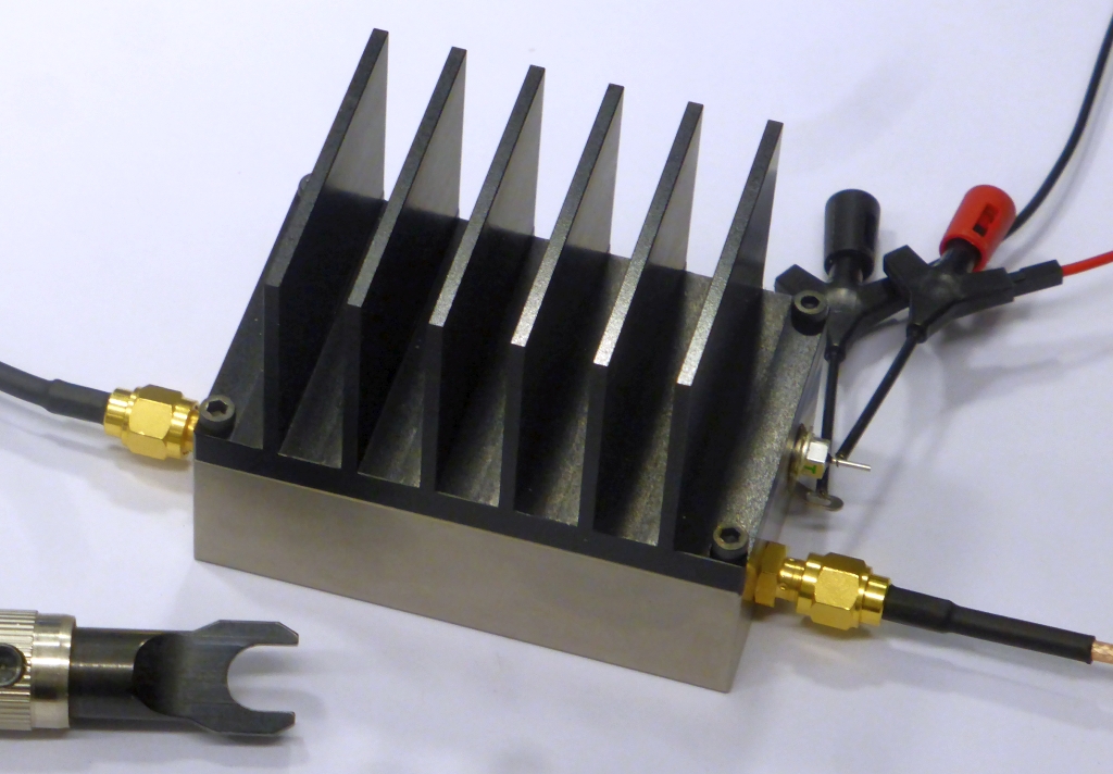
The assembled prototype. Pure Power !
✈ Motivation
RF-Amplifiers is the thing coming directly after Power Supplies. You never can have enough of them.
Especially broadband High Power Amplifiers. Because this would allow you to use antennas with low
efficiency. (We are not clumsy antenna builders, but often space restricts the design).
Specifications :
Specifications :
| Frequency Range | 2 - 2500 MHz |
| Gain | 17 dB |
| Output Power | +30 dBm (1 Watt) @ 1 dB Compression |
| DC supply voltage | 15 V, 350 mA |
✈ The Design
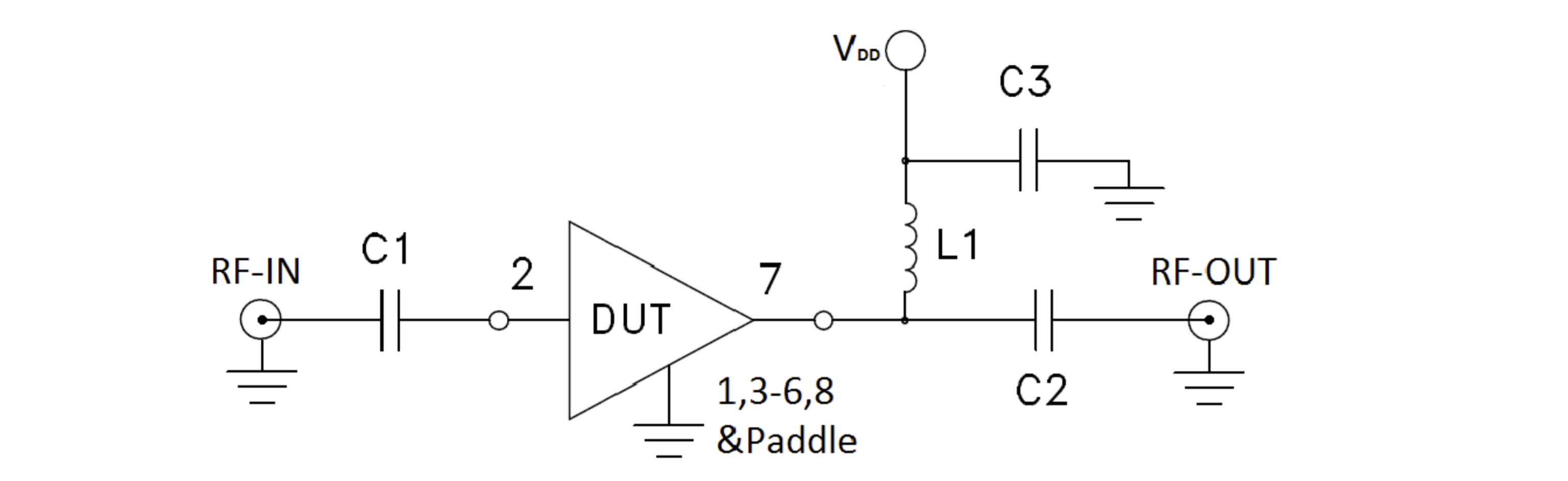
Recommended Application Circuit courtesy of Mini Circuits
The Design is actually very classic. It follows the standard open-collector Gain-Block scheme found in many other amplifier designs. There is no Voltage regulator included, as it is designed for the usual +15 V supplies, beeing present almost everywhere in our labs. Instead of a big resistor for current-limiting, we use twelve 1 Ω resistors, 1206 to do the job. The wideband choke L1 is a 5.6 µH from Coilcraft, beeing able to withstand currents of up to 700 mA in the range of 30 – 3000 MHz. And the Heatsink is custom designed to fit our standard Case No 3. A small hole under the amplifier chip has been introduced to allow for hand-soldering of the device.
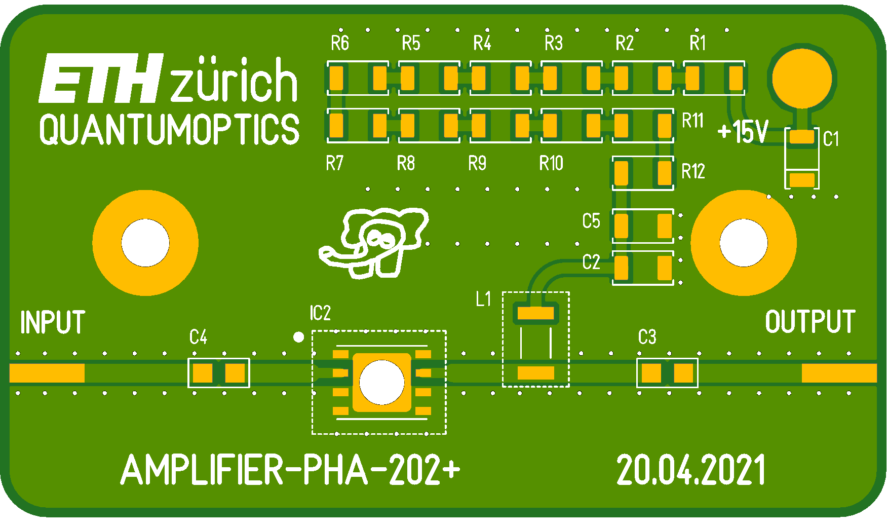
"The Hole" - a disaster for Reflow Soldering, but a genious strike when Hand Soldering.
The design uses Coplanar Waveguides. For our FR4, 1.5 mm thick, we use traces with 1.27 mm width and a gap of 0.23 mm. This works nice with the 0805 sized coupling capacitors.
✈ Downloads


✈ Performance
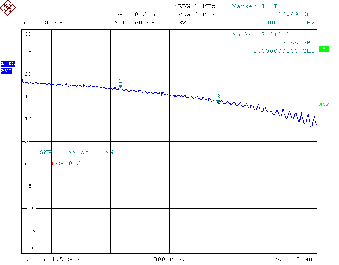
S21, measured with a Spectrum Analyser with Tracking Generator. Input Power was 0 dBm. Some ripple above 2 GHz indicates an impedance offset.
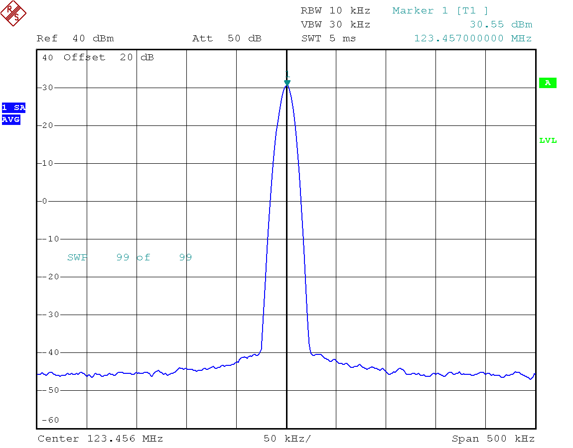
+30 dBm (1 W) is easily reached on all HF/VHF/UHF QO-Bands.

S11 is better than 10 dB up to 2.5 GHz. Not too shabby :-)
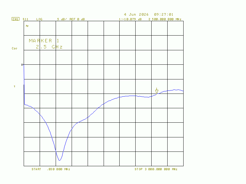
S22 is similiar - at least 10 dB up to 2.5 GHz
✈ Credits • Note of Thanks
We would like to thank the highly motivated staff of Coilcraft for their efforts to supply us
(our research group at ETH zürich)
with free samples.
ขอขอบพระคุณทุกท่าน.
ขอขอบพระคุณทุกท่าน.
Problems with heat ??? No, thanks to Andi and Team from our brilliant workshop.
✈ Share your thoughts
The webmaster does not read these comments regularely. Urgent questions should be send via email.
Ads or links to completely uncorrelated things will be removed.
|
t1 = 7319 d
t2 = 291 ms |
★ ★ ★ Copyright © 2006 - 2026 by changpuak.ch ★ ★ ★
|

|