 ช้างเผือก
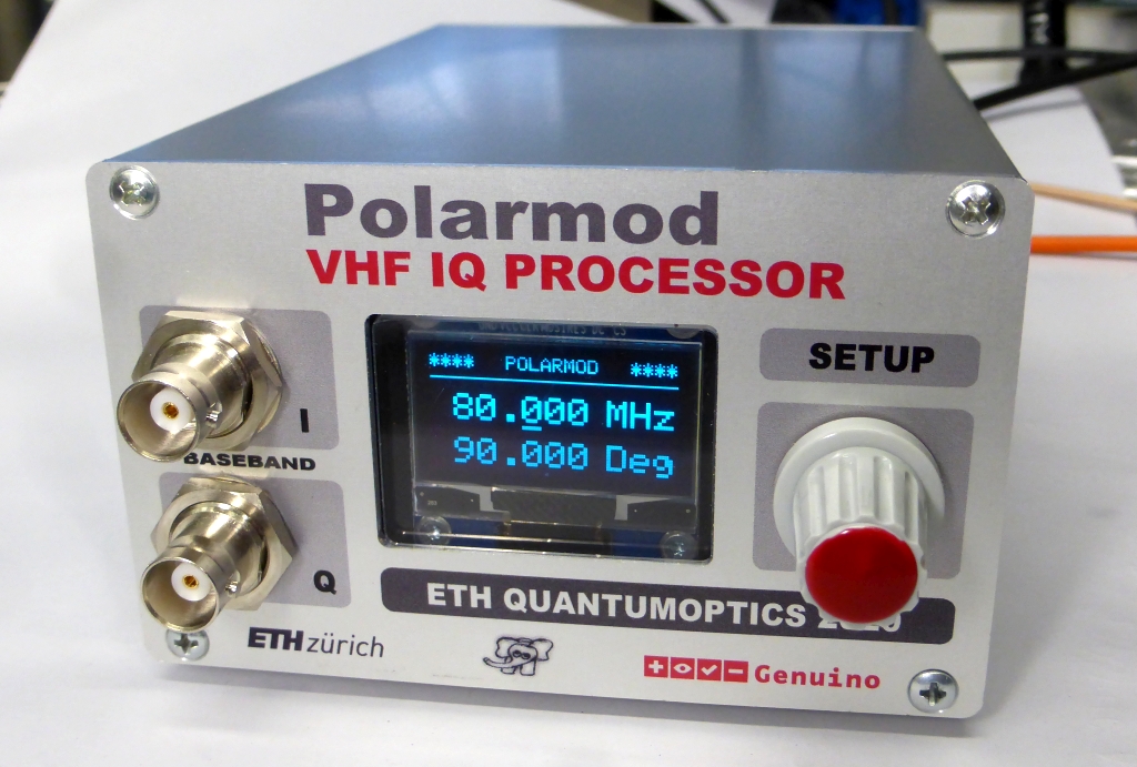
Categories
Statistics
Since 08.08.2014
Counts only, if "DNT = disabled".
216.73.216.253
216.73.216.253
Counts only, if "DNT = disabled".
216.73.216.253
216.73.216.253
Info

เราจะทำแบบวิศวกรผู้ยิ่งใหญ่

27. July 2026
YOUR OPINION •••
average: 1.000, n: 5

When using this form, your ip is stored in order to avoid multiple voting on the same website. That's it.
When using this form, your ip is stored in order to avoid multiple voting on the same website. That's it.
Arduino-Polarmod.php 24055 Bytes 04-03-2025 19:11:01
Arduino/Genuino "Polarmod"
An I/Q Downconverter (Demodulator) with the AD9958
The assembled prototype
✈ Motivation
This project was created to replace a huge setup with quite a lot of Mini Circuits stuff,
consuming a lot of valuable labspace. Now we have a neat little converter, shifting almost anything
in the range of our NI-cards input space. Design inspired by the Impact - Team. And locked to
an external 10 MHz source.
✈ Block Diagam
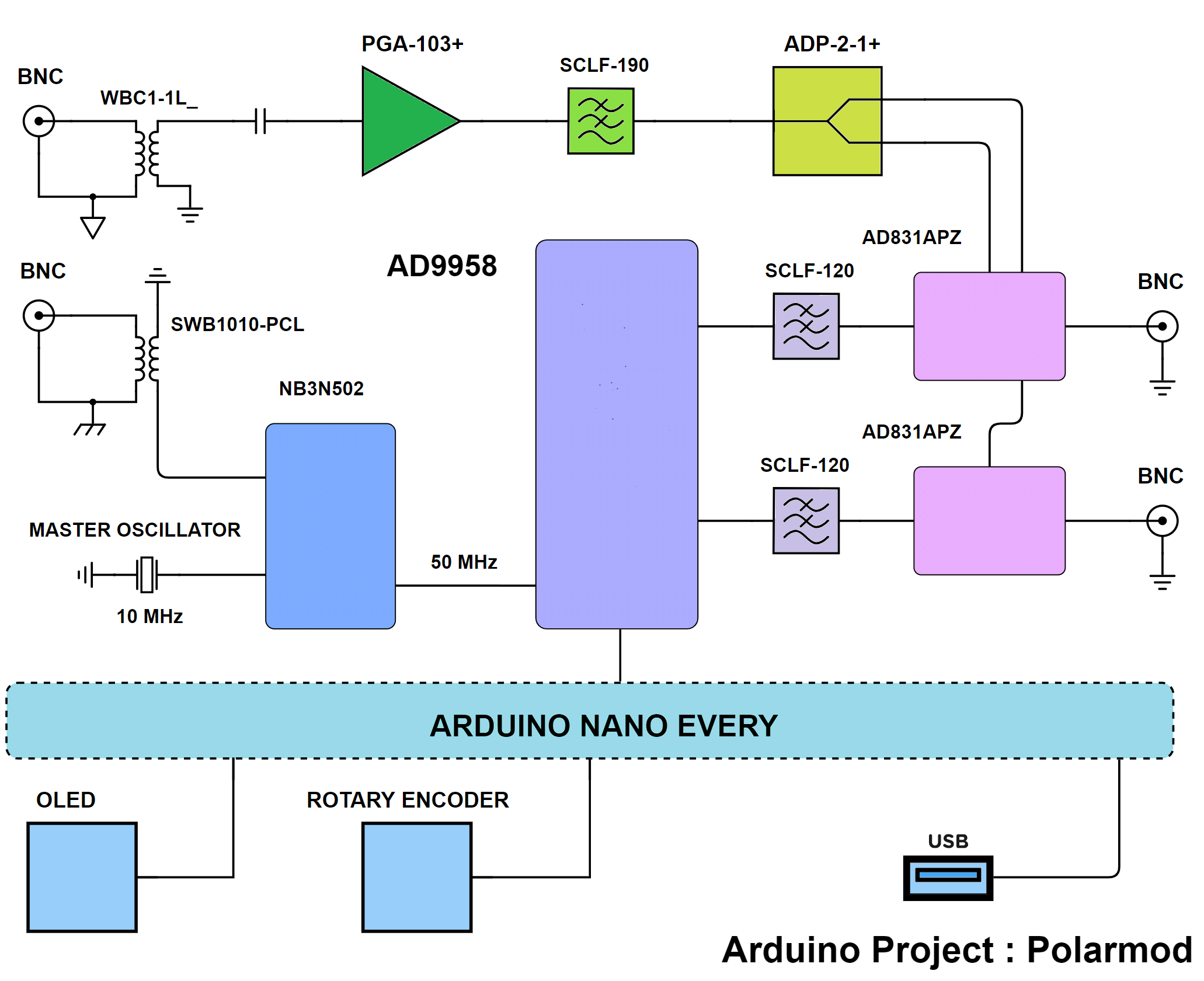
Block Diagram of the Polarmodmod
The Polarmod has two BNC sockets at the rearpanel. Both are galvanically isolated by transformers. One is used for the RF Signal. It can range from 10 MHz to approx. 199 MHz. The second one is for a 10 MHz Reference Clock. If available, it is used to synchronise the 50 MHz to an external Frequency Standard.
The RF Input is then amplified by an ultra Low Noise Preamplifier, built around the PGA-103+ from Mini Circuits. It's output is split and fed to two Mixers. We used the AD831 here. Detailed description below.
The LO, used for those two mixers is generated by a DDS. An AD9958, because it has two outputs and those two outputs can be programmed to have a well defined phase relative to each other.
And yes, all is controlled by an Arduino Nano Every, visualised by a small OLED and the Operator can communicate via a Rotary Encoder with that thing. USB communication is also possible.
Specifications :
| Frequency range | 1 MHz to 199 MHz |
| Frequency tuning | menu-controlled in 1 kHz steps |
| Phase range | 0 ... 359.9 ° |
| Phase tuning | menu-controlled in 0.1 degree steps |
| Max. RF at Input | - 25 dBm |
| DC supply voltage | 12 V +25/-0 %, approx. 599 mA |
✈ Reference Clock Generation
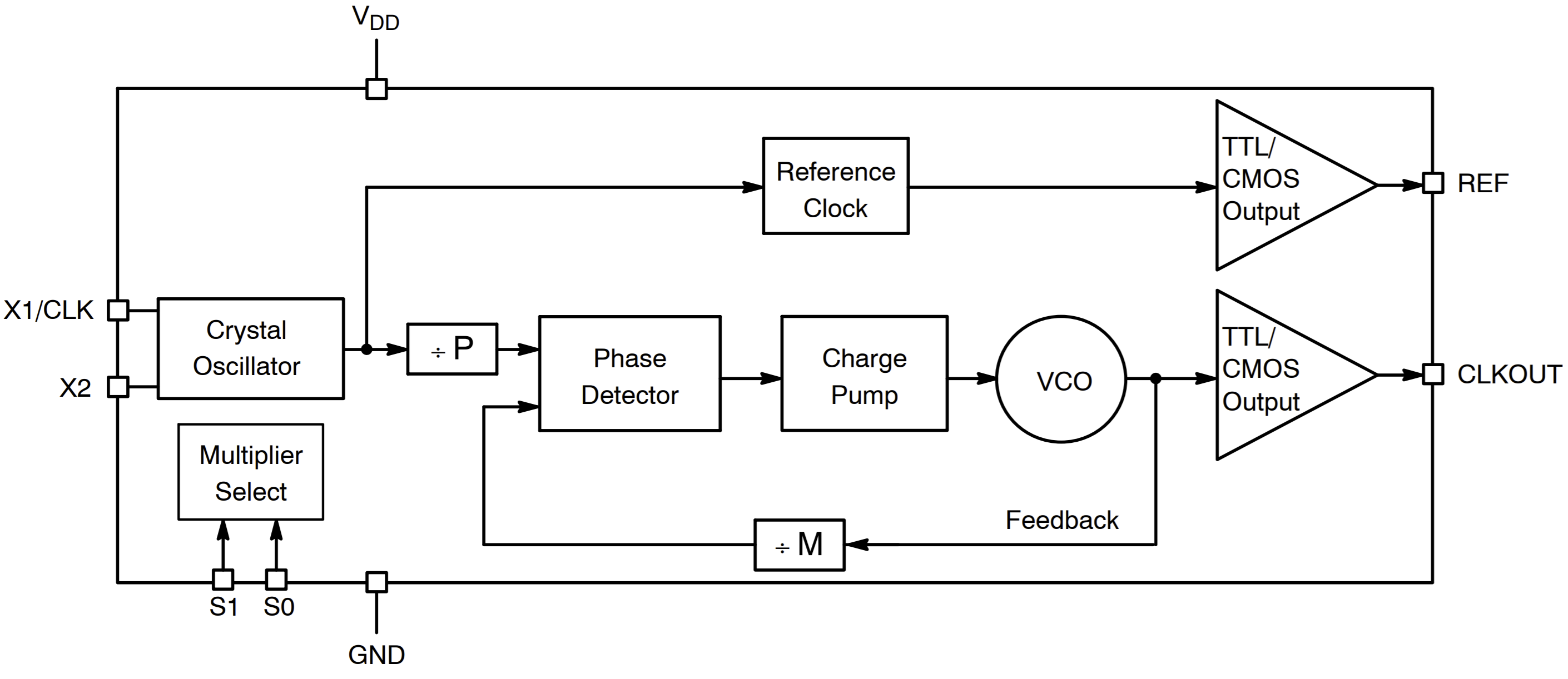
NB3N502 Logic Diagram, Drawing Courtesy of ON Semiconductor
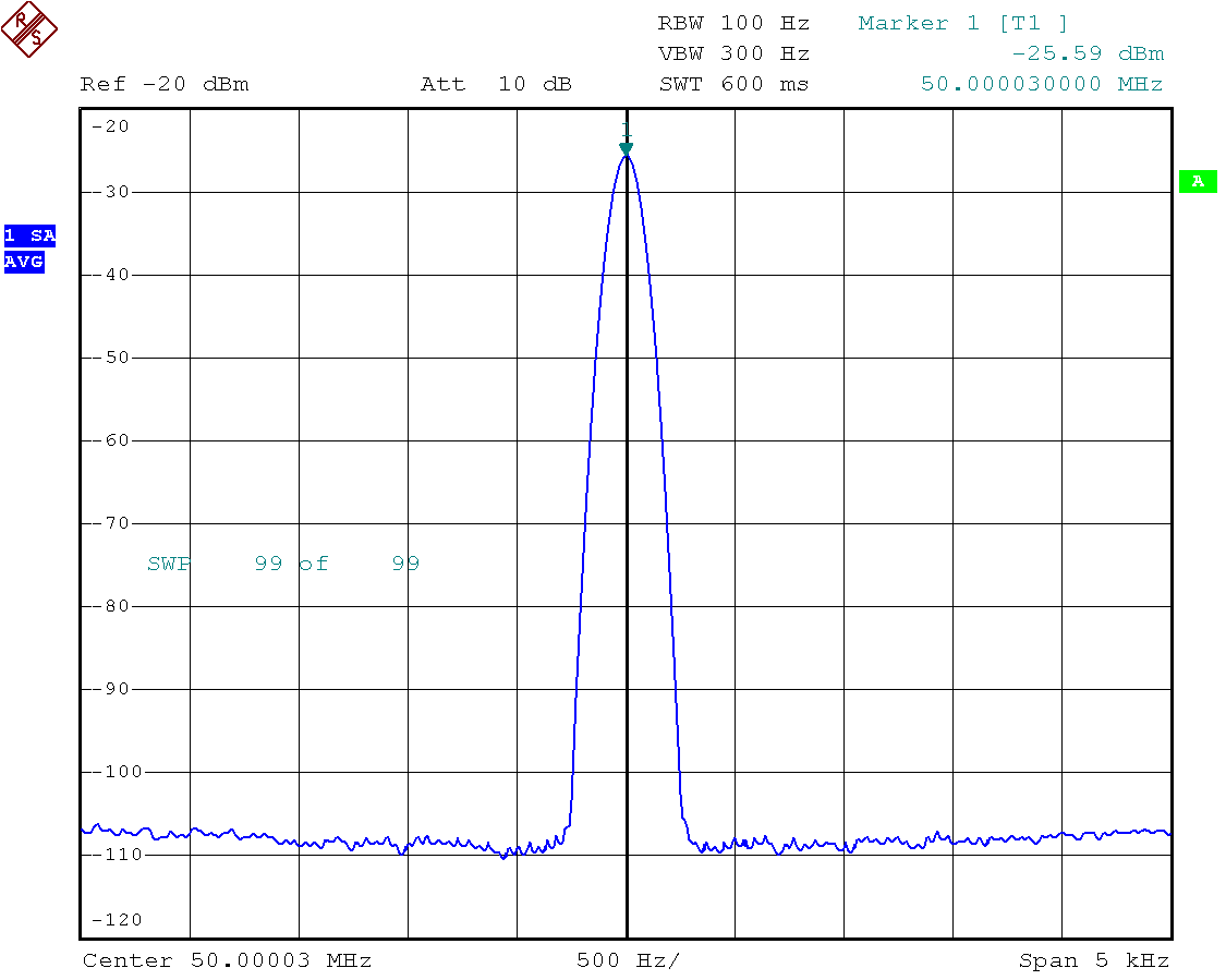
The Reference Clock is geneated by a NB3N502 (14 MHz to 190 MHz PLL Clock Multiplier). It uses a 10 MHz Crystal and multiplies this by a factor of 5 to generate and intermediate frequency of 50 MHz. In case an external 10 MHz Reference Signal is connected, this is injected into the oscillator.
The 50 MHz are used as a Reference for the PLL Multipier in the AD9958. It is multiplied by 10 to create a 500 MHz Clock for the DDS. The VCO uses the High Range (VCO gain control = 1, system clock above 255 MHz). The charge pump current is set to 75 µA.
✈ Mixer
The Mixer used is an AD831 (twice). It is a low distortion, wide dynamic range, monolithic
mixer for use in such applications as RF to IF downconversion
in HF and VHF receivers. Says the datasheet. It was chosen, because it has buffers at the input,
so a variation in LO-level does not affect the operation (much). Indeed, it needs only - 10 dBm
of LO-Power.
The 10.3 dB Noise Figure do not degrade the system performance much, as we use a Low Noise Input Amplifier made with a PGA-103+ from Minicircuits. (0.5 dB NF, 22 dB Gain)
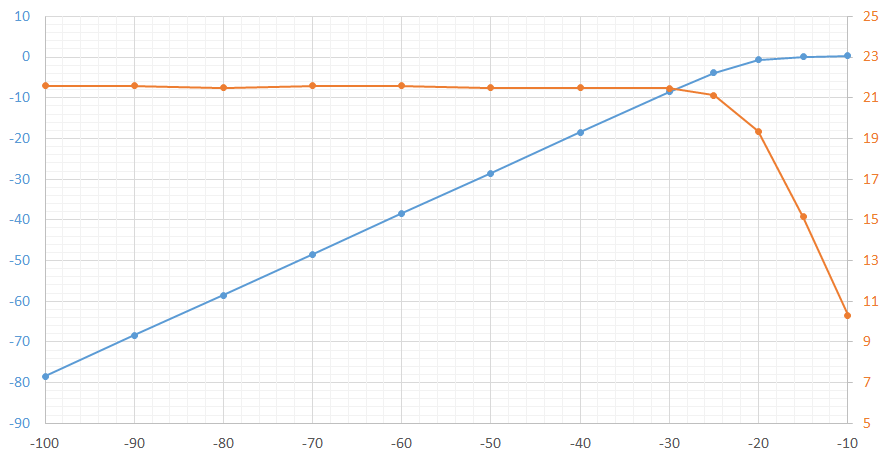
Conversion Gain (orange) is 21.5 dB. Compression (blue) starts at approx. - 25 dBm
Horizontal : Input [dBm], Vertical : Output [dBm] and Gain [dB]. Measured at 80 MHz.
The 10.3 dB Noise Figure do not degrade the system performance much, as we use a Low Noise Input Amplifier made with a PGA-103+ from Minicircuits. (0.5 dB NF, 22 dB Gain)
Conversion Gain (orange) is 21.5 dB. Compression (blue) starts at approx. - 25 dBm
Horizontal : Input [dBm], Vertical : Output [dBm] and Gain [dB]. Measured at 80 MHz.
✈ Downloads


✈ Test Sketch for Arduino/Genuino Nano Every
Double click on code to select ...
/* //////////////////////////////////////////////////////////////////

  ARDUINO/Genuino Project "POLARMOD", an I-Q DOWNCONVERTER
  https://www.changpuak.ch/electronics/Arduino-Polarmod.php
  Software Version 1.0
  12.12.2020 by ALEXANDER SSE FRANK

////////////////////////////////////////////////////////////////// */

#include <Wire.h>
#include <Adafruit_GFX.h>
#include <Adafruit_SH1106.h>


// DISPLAY
#define OLED_MOSI  A2
#define OLED_CLK   A3
#define OLED_DC    A0
#define OLED_CS    13
#define OLED_RESET A1

// ROTARY ENCODER
const int RotaryEncoder1 = A7 ;   // PRESSED
const int RotaryEncoder2 = 2 ;
const int RotaryEncoder3 = 3 ;
volatile boolean LEFT = false ;
volatile boolean RIGHT = false ;
volatile boolean READY = true ;

// DDS VARIABLES
double FREQ = 80.0 ;
double PHASE = 90.0 ;
const double FREQ_MAX = 200.001 ;
const double FREQ_MIN = 0.999 ;
const double PHASE_MIN = 0.0 ;
const double PHASE_MAX = 359.9 ;

int CursorPos = 3 ;
const double REF = 500.000000 ;

Adafruit_SH1106 display(OLED_MOSI,OLED_CLK,OLED_DC,OLED_RESET,OLED_CS);

#if (SH1106_LCDHEIGHT != 64)
#error("Height incorrect, please fix Adafruit_SH1106.h!");
#endif


// /////////////////////////////////////////////////////////////
// Serial Communication Routines : EEPROM & DDS
// /////////////////////////////////////////////////////////////

#define EEPROM_24C01_I2CADDR 0x50

// Single-bit serial 2-wire mode
int DDS_RESET = 5 ;   // Active High Reset Pin
int DDS_SYNCIO = 6 ;
int DDS_SDIO2 = 7 ;
int DDS_SDIO1 = 8 ;
int DDS_SDAT = 9 ;
int DDS_SCLK = 10 ;
int DDS_CS = 11 ;
int DDS_IO_UPDATE = 12 ;


// ///////////////////////////////////////
void ResetDDS()
// ///////////////////////////////////////

{
  digitalWrite(DDS_RESET, HIGH) ;
  delay(9) ;
  digitalWrite(DDS_RESET, LOW) ;
  delay(9) ;
}


// //////////////////////////////////////////////////////////
void Energy()
// //////////////////////////////////////////////////////////

{
  digitalWrite(DDS_IO_UPDATE, HIGH) ;
  delay(1) ;
  digitalWrite(DDS_IO_UPDATE, LOW) ;
}


// //////////////////////////////////////////////////////////
void WriteDDS1(byte instruct, byte d1)
// //////////////////////////////////////////////////////////

{
  digitalWrite(DDS_CS, LOW) ;
  shiftOut(DDS_SDAT, DDS_SCLK, MSBFIRST, instruct) ;
  shiftOut(DDS_SDAT, DDS_SCLK, MSBFIRST, d1) ;
  digitalWrite(DDS_CS, HIGH) ;
}


// //////////////////////////////////////////////////////////
void WriteDDS2(byte instruct, byte d1, byte d2)
// //////////////////////////////////////////////////////////

{
  digitalWrite(DDS_CS, LOW) ;
  shiftOut(DDS_SDAT, DDS_SCLK, MSBFIRST, instruct) ;
  shiftOut(DDS_SDAT, DDS_SCLK, MSBFIRST, d1) ;
  shiftOut(DDS_SDAT, DDS_SCLK, MSBFIRST, d2) ;
  digitalWrite(DDS_CS, HIGH) ;
}


// //////////////////////////////////////////////////////////
void WriteDDS3(byte instruct, byte d1, byte d2, byte d3)
// //////////////////////////////////////////////////////////

{
  digitalWrite(DDS_CS, LOW) ;
  shiftOut(DDS_SDAT, DDS_SCLK, MSBFIRST, instruct) ;
  shiftOut(DDS_SDAT, DDS_SCLK, MSBFIRST, d1) ;
  shiftOut(DDS_SDAT, DDS_SCLK, MSBFIRST, d2) ;
  shiftOut(DDS_SDAT, DDS_SCLK, MSBFIRST, d3) ;
  digitalWrite(DDS_CS, HIGH) ;
}


// //////////////////////////////////////////////////////////
void WriteDDS4(byte instruct,byte d1,byte d2,byte d3,byte d4)
// //////////////////////////////////////////////////////////

{
  digitalWrite(DDS_CS, LOW) ;
  shiftOut(DDS_SDAT, DDS_SCLK, MSBFIRST, instruct) ;
  shiftOut(DDS_SDAT, DDS_SCLK, MSBFIRST, d1) ;
  shiftOut(DDS_SDAT, DDS_SCLK, MSBFIRST, d2) ;
  shiftOut(DDS_SDAT, DDS_SCLK, MSBFIRST, d3) ;
  shiftOut(DDS_SDAT, DDS_SCLK, MSBFIRST, d4) ;
  digitalWrite(DDS_CS, HIGH) ;
}


// //////////////////////////////////////////////////////////
void UpdateFTW()
// //////////////////////////////////////////////////////////

{
  int Byte1, Byte2, Byte3, Byte4 ;
  // DATASHEET PAGE 18
  // fout = FTW * fs / 2^32
  // fs / 2^32 is constant. = 0.000000116415321826934814453125
  // 2^32 / fs is constant. = 8’589’934.592

  // METHODE 1 .:. float * const float
  unsigned long  FTW = (unsigned long)(FREQ * 8589934.592 ) ;
  Byte1 = (0xFF000000 & FTW) >> 24 ;
  Byte2 = (0x00FF0000 & FTW) >> 16 ;
  Byte3 = (0x0000FF00 & FTW) >> 8 ;
  Byte4 = (0x000000FF & FTW) ;
  Serial.print(FREQ,3) ;
  Serial.print(" MHz, ") ;
  Serial.println(FTW,DEC) ;

  // CHANNEL 0 + CHANNEL 1
  WriteDDS1(0x00, 0xF0) ;
  WriteDDS4(0x04, Byte1, Byte2, Byte3, Byte4) ;
  Energy() ;
}


// //////////////////////////////////////////////////////////
void UpdatePTW()
// //////////////////////////////////////////////////////////

{
  // EVERY CHANNEL HAS ITS OWN !!
  // SEE PAGE 39 OF DATASHEET
  // CHANNEL 0 : CSR = 0x70
  // CHANNEL 1 : CSR = 0xB0
  // DATASHEET PAGE 18
  // pout = POW * 360 / 2^14
  // POW = pout * 2^14 / 360
  // 360 / 2^14 is constant. = 0.02197265625
  // 2^14 / 360 is constant. = 16384 / 360 = 45.51111111111

  unsigned long  POW = (int)( PHASE * 45.51111111111111 ) ;
  // Serial.print(PHASE, 1) ;
  // Serial.print(",") ;
  // Serial.println(POW, DEC) ;
  int EMSB ;
  int ELSB ;
  EMSB = (POW & 0x3F00) >> 8 ;
  ELSB = (POW & 0x00FF) ;
  // CHANNEL 0
  WriteDDS1(0x00, 0x70) ;
  WriteDDS2(0x05, 0x00, 0x00) ;
  Energy() ;
  // CHANNEL 1
  WriteDDS1(0x00, 0xB0) ;
  WriteDDS2(0x05, EMSB, ELSB) ;
  Energy() ;
}

// /////////////////////////////////////////////////////////////
// ANALOG INPUTS
// /////////////////////////////////////////////////////////////

const double SupplyFactor = ( 14.4 * 5.0 ) / (1024 * 2.4 ) ;
double SUPPLY_ARD_VOLT = 0.0 ;
int SUPPLY_ARD_PIN = A7 ;
double SUPPLY_MULTIPLIER = 4.0 ;

void UpDateSupplyVoltage()
{
  SUPPLY_ARD_VOLT = SupplyFactor * analogRead(SUPPLY_ARD_PIN) ;
}


// /////////////////////////////////////////////////////////////
// SUBROUTINES DISPLAY.
// /////////////////////////////////////////////////////////////

void UpdateDisplay()
{
  // unsigned long  StartProcedure = millis() ;
  display.clearDisplay();
  display.setTextSize(1);
  display.setTextColor(WHITE);
  display.setCursor(0,0); display.print("****");
  display.setCursor(40,0); display.print("POLARMOD");
  display.setCursor(104,0); display.print("****");
  display.drawLine(0, 12, 128, 12, WHITE);
  display.setTextSize(2);
  // FREQUENCY
  display.setCursor(0, 21);
  if (FREQ < 100.000) display.print(" ");
  if (FREQ < 10.000) display.print(" ");
  display.print(FREQ,3);
  display.setCursor(92, 21);
  display.print("MHz");
  // PHASE
  if (PHASE < 0.000) PHASE *= -1.0 ;
  display.setCursor(0, 45);
  if (PHASE < 100.000) display.print(" ");
  if (PHASE < 10.000) display.print(" ");
  display.print(PHASE,3);
  // display.setCursor(92, 41);
  // display.print("o");
  display.setCursor(92, 45);
  display.print("Deg");

  // CURSOR
  if(CursorPos <= 5) display.setCursor(0, 25);
  if(CursorPos == 1) display.print(" ");
  if(CursorPos == 2) display.print("  ");
  if(CursorPos == 3) display.print("    ");
  if(CursorPos == 4) display.print("     ");
  if(CursorPos == 5) display.print("      ");
  if(CursorPos > 5)  display.setCursor(0, 49);
  if(CursorPos == 6) display.print(" ");
  if(CursorPos == 7) display.print("  ");
  if(CursorPos == 8) display.print("    ");
  display.print("_");
  display.display();
  // Serial.println(millis()-StartProcedure,DEC);

}

// /////////////////////////////////////////////////////////////
// S E T U P
// /////////////////////////////////////////////////////////////

void setup()
{
  Serial.begin(115200) ;

  Wire.begin() ;

  // INIT OLED
  display.begin(SH1106_SWITCHCAPVCC);

  // SHOW STARTUP SCREEN
  display.clearDisplay();
  display.setTextSize(1);
  display.setTextColor(WHITE);
  display.setCursor(0,0); display.print("****");
  display.setCursor(40,0); display.print("POLARMOD");
  display.setCursor(104,0); display.print("****");
  display.drawLine(0, 12, 128, 12, WHITE);
  display.setTextSize(1);
  display.setCursor(0, 21);
  display.println("AN I-Q-DOWNCONVERTER");
  display.setCursor(0, 33);
  display.println("FOR LABORATORY USE.");
  display.setCursor(0, 45);
  display.println("(C) ETH QUANTUMOPTICS");
  display.setCursor(0, 57);
  display.println("BUILT 05.12.2020");
  display.display();

  delay(999) ;

  pinMode(RotaryEncoder1, INPUT_PULLUP);
  pinMode(RotaryEncoder2, INPUT_PULLUP);
  pinMode(RotaryEncoder3, INPUT_PULLUP);
  // YELLOW
  attachInterrupt(digitalPinToInterrupt(RotaryEncoder2),
  RotaryEncoderISR2, FALLING);
  // GREEN
  attachInterrupt(digitalPinToInterrupt(RotaryEncoder3),
  RotaryEncoderISR3, FALLING);

  delay(999);


  pinMode(DDS_RESET, OUTPUT) ;
  pinMode(DDS_SYNCIO, OUTPUT) ;
  digitalWrite(DDS_SYNCIO, LOW) ;
  pinMode(DDS_SDIO2, INPUT) ;
  pinMode(DDS_SDIO1, INPUT) ;
  pinMode(DDS_SDAT, OUTPUT) ;
  pinMode(DDS_SCLK, OUTPUT) ;
  pinMode(DDS_CS, OUTPUT) ;
  digitalWrite(DDS_CS, HIGH) ;
  pinMode(DDS_IO_UPDATE, OUTPUT) ;
  digitalWrite(DDS_IO_UPDATE, LOW) ;


  // INIT DDS
  ResetDDS() ;

  // Channel Select Register (CSR) (0x00) = BOTH
  WriteDDS1(0x00, 0xF0) ;

  // Function Register 1 (FR1) (0x01) USES 50 MHz CRYSTAL
  WriteDDS3(0x01, 0xA8, 0x00, 0x00) ;

  // Function Register 2 (FR2) (0x02)
  WriteDDS2(0x02, 0x00, 0x00) ;

  // Channel Function Register (CFR) (0x03)
  WriteDDS3(0x03, 0x00, 0x03, 0x00) ;

  // Channel Frequency Tuning Word (CFTW0) (0x05)
  UpdateFTW() ;

  // Amplitude Control Register (ACR) (0x06)
  // WriteDDS3(0x06, 0x00, 0x13, 0xFF) ;

  Energy() ;

  UpdatePTW() ;
}


// /////////////////////////////////////////////////////////////
// M A I N L O O P
// /////////////////////////////////////////////////////////////

void loop()
{
  // KEY ROTATED ?
  // //////////////////////////////////
  if(LEFT)
  // //////////////////////////////////
  {
    READY = false ;
    switch (CursorPos)
    {
      case 0:
        if(FREQ >= (FREQ_MIN + 100.0)) FREQ -= 100.0 ;
        UpdateFTW() ;
        break;
      case 1:
        if(FREQ >= (FREQ_MIN + 10.0)) FREQ -= 10.0 ;
        UpdateFTW() ;
        break;
      case 2:
        if(FREQ >= (FREQ_MIN + 1.0)) FREQ -= 1.0 ;
        UpdateFTW() ;
        break;
      case 3:
        if(FREQ >= (FREQ_MIN + 0.1)) FREQ -= 0.1 ;
        UpdateFTW() ;
        break;
      case 4:
        if(FREQ >= (FREQ_MIN + 0.01)) FREQ -= 0.01 ;
        UpdateFTW() ;
        break;
      case 5:
        if(FREQ >= (FREQ_MIN + 0.001)) FREQ -= 0.001 ;
        UpdateFTW() ;
        break;
      case 6:
        if(PHASE >= (PHASE_MIN + 10.0)) PHASE -= 10.0 ;
        UpdatePTW() ;
        break;
      case 7:
        if(PHASE >= (PHASE_MIN + 1.0)) PHASE -= 1.0 ;
        UpdatePTW() ;
        break;
      case 8:
        if(PHASE >= (PHASE_MIN + 0.1)) PHASE -= 0.1 ;
        UpdatePTW() ;
        break;
   }
   READY = true ;
   LEFT = false ;
   RIGHT = false ;
  }
  // //////////////////////////////////
  if(RIGHT)
  // //////////////////////////////////
  {
    READY = false ;
    switch (CursorPos)
    {
      case 0:
        if(FREQ <= (FREQ_MAX - 100.0)) FREQ += 100.0 ;
        UpdateFTW() ;
        break;
      case 1:
        if(FREQ <= (FREQ_MAX - 10.0)) FREQ += 10.0 ;
        UpdateFTW() ;
        break;
      case 2:
        if(FREQ <= (FREQ_MAX - 1.0)) FREQ += 1.0 ;
        UpdateFTW() ;
        break;
      case 3:
        if(FREQ <= (FREQ_MAX - 0.1)) FREQ += 0.1 ;
        UpdateFTW() ;
        break;
      case 4:
        if(FREQ <= (FREQ_MAX - 0.01)) FREQ += 0.01 ;
        UpdateFTW() ;
        break;
      case 5:
        if(FREQ <= (FREQ_MAX - 0.001)) FREQ += 0.001 ;
        UpdateFTW() ;
        break;
      case 6:
        if(PHASE <= (PHASE_MAX - 10.0)) PHASE += 10.0 ;
        UpdatePTW() ;
        break;
      case 7:
        if(PHASE <= (PHASE_MAX - 1.0)) PHASE += 1.0 ;
        UpdatePTW() ;
        break;
      case 8:
        if(PHASE <= (PHASE_MAX - 0.1)) PHASE += 0.1 ;
        UpdatePTW() ;
        break;
   }
   READY = true ;
   LEFT = false ;
   RIGHT = false ;
  }

  // //////////////////////////////////
  // KEY PRESSED ?
  // //////////////////////////////////
  if(digitalRead(RotaryEncoder1) == LOW)
  {
    CursorPos += 1 ;
    if(CursorPos > 8) CursorPos = 0 ;
  }

  UpdateDisplay() ; // 50 ms

  delay(149) ;
}


// /////////////////////////////////////////////////////////////
// INTERRUPT SERVICE ROUTINES
// /////////////////////////////////////////////////////////////

void RotaryEncoderISR2()
{
  // YELLOW
  if(READY)
  {
  LEFT = false ;
  RIGHT = false ;
  byte autre = digitalRead(RotaryEncoder3) ;
  if (autre > 0) RIGHT = true ;
  if (autre < 1) LEFT = true ;
  }
}

void RotaryEncoderISR3()
{
  // GREEN
  if(READY)
  {
  LEFT = false ;
  RIGHT = false ;
  byte autre = digitalRead(RotaryEncoder2) ;
  if (autre > 0) LEFT = true ;
  if (autre < 1) RIGHT = true ;
  }
}


// /////////////////////////////////////////////////////////////
// END OF FILE.
// /////////////////////////////////////////////////////////////
✈ What's all this I and Q stuff anyhow ???
✈ Share your thoughts
The webmaster does not read these comments regularely. Urgent questions should be send via email.
Ads or links to completely uncorrelated things will be removed.
|
t1 = 7319 d
t2 = 269 ms |
★ ★ ★ Copyright © 2006 - 2026 by changpuak.ch ★ ★ ★
|

|