 ช้างเผือก
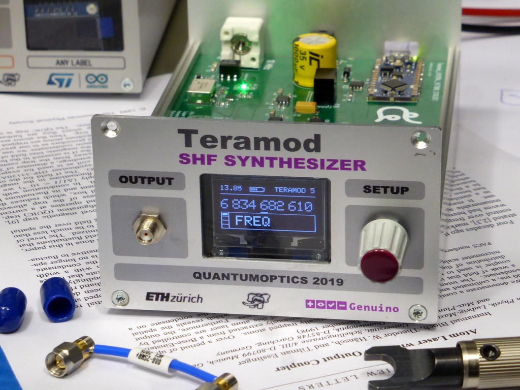
Categories
Statistics
Since 08.08.2014
Counts only, if "DNT = disabled".
216.73.216.253
216.73.216.253
Counts only, if "DNT = disabled".
216.73.216.253
216.73.216.253
Info

King Chulalongkorn

27. July 2026
YOUR OPINION •••
average: 1.000, n: 1

When using this form, your ip is stored in order to avoid multiple voting on the same website. That's it.
When using this form, your ip is stored in order to avoid multiple voting on the same website. That's it.
Anthem of the Chulalongkorn University, Bangkok (Thailand)
Arduino-Shield-CHULA.php 5555 Bytes 23-10-2019 23:10:19
Arduino/Genuino DIY SHF Synthesizer "TERAMOD"
Shield "CHULA", in memoriam King Chulalongkorn of Siam
This is a shield to generate super high frequencies with the LMX2594.
Together with a step attenuator and an amplifier this makes a great synthesizer.
From 2 GHz up to 9.999 GHz.
And yes, we are bold enough to approach this project with FR4. (4-Layer). This design mostly uses 0402 components. If you don't have a microscope, replication is going to be challenging.
From 2 GHz up to 9.999 GHz.
And yes, we are bold enough to approach this project with FR4. (4-Layer). This design mostly uses 0402 components. If you don't have a microscope, replication is going to be challenging.
✈ The building Blocks • Functional Description
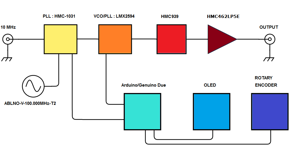
The mastermind of this design is of course the Arduino Nano Every. It handles the user input from the rotary encoder and displays the status on the 128 x 64 px oled display. The Nano also programs the LMX2594 (VCO/PLL), which is the workhorse of this generator.
The LMX2594 has 2 differential outputs which are almost identical. We need only one, and from this one only a single output, as broadband transformers for this frequency range are extremely hard to find. (We are in the year 2019 :-)
Directly after the LMX2594 is an attenuator (HMC939, 1.0 dB LSB GaAs MMIC 5-BIT DIGITAL ATTENUATOR, 0.1 - 33 GHz). As the name suggests, it is from Hittite/Analog Devices.
Finally an amplifier (HMC462 from Hittite/Analog Devices) shall increase the signal level to +10 dBm. This amplifier has the advantage, that the bias is built in already. Unfortunately this limits also the output frequency range, as the minimum frequency is 2 GHz. See "Hints" for more information.
The device is equipped with a VCXO running at 100 MHz. It needs a stable 10 MHz at the rear BNC connector. In case that is not provided, the VCXO runs at 99.997058 MHz. As the Lock-Status is monitored by the Arduino, one could compensate for that. We don't do that. We lock it.
The device is powered by a 9 V, 800 mA Plug-in power supply.
| Frequency Range | 2 GHz to 15 GHz |
| Resolution | 1 Hz (datasheet says 47 mHz is possible, but the display says 1 Hz is enough) |
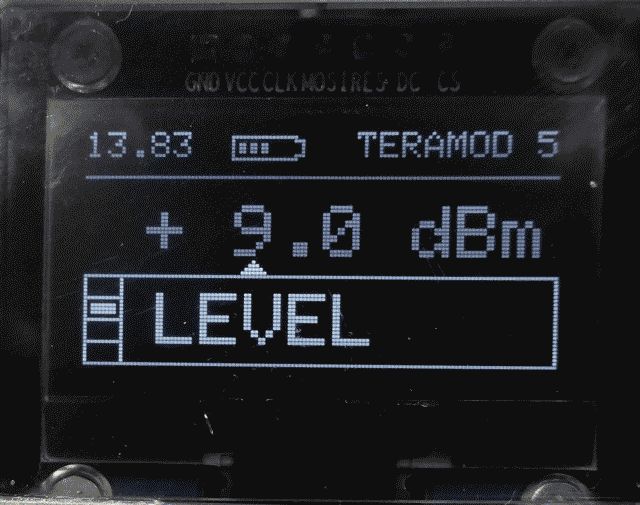
| Output Power | -20 ... +10 dBm, in 1 dB steps |
| DC supply voltage | 9 V ... 19 V, less than 999 mA |
✈ The workhorse : LMX2594
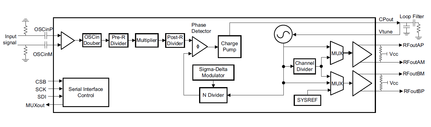
Inside the chip, courtesy of Texas Instruments
"The LMX2594 is a high-performance, wideband frequency synthesizer with integrated VCO and output divider. The VCO operates from 7.5 GHz to 15 GHz, and this can be combined with the output divider to produce any frequency in the range of 10 MHz to 15 GHz. Within the input path, there are two dividers and a multiplier for flexible frequency planning. The multiplier also allows the reduction of spurs by moving the frequencies away from the integer boundary. The PLL is fractional-N PLL with a programmable delta-sigma modulator up to 4th order. The fractional denominator is a programmable 32-bit long, which can easily provide fine frequency steps below 1-Hz resolution". Says the datasheet.
✈ Assembly
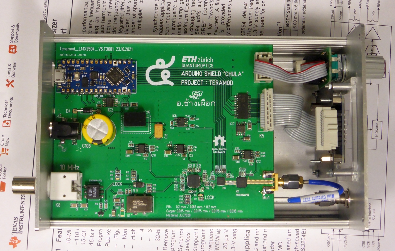
Inside the case of the Synthesizer "TERAMOD" : the shield "Chula".
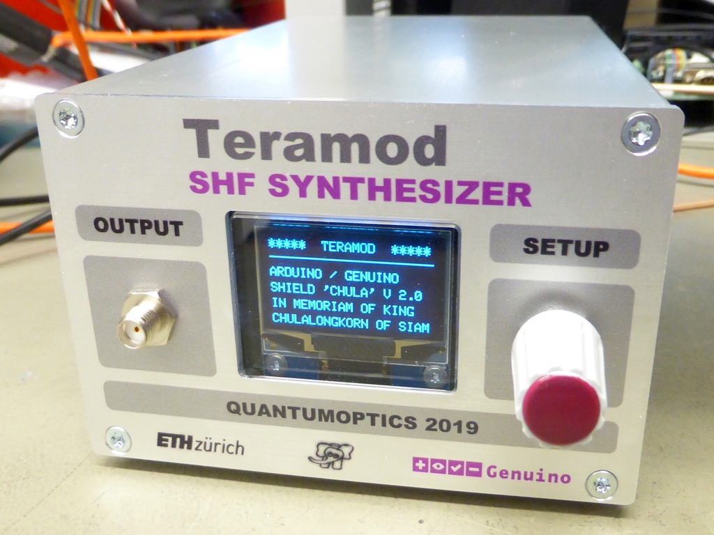
Front view of the Synthesiser "TERAMOD", the colour was actually more pink ...
✈ Downloads


✈ Arduino Sketch - The Code
Double click on code to select ...
/* //////////////////////////////////////////////////////////////////
ARDUINO/Genuino Due Sketch for "CHULA", Project "TERAMOD"
https://www.changpuak.ch/electronics/Arduino-Shield-CHULA.php
LMX2594 2...15 GHz Wideband PLLATINUM™ RF Synthesizer
Lower limit defined by amplifier, HMC462 from Hittite/Analog Devices
Software Version 5.1
28.07.2019, Alexander Sse Frank
USEFUL:
learn.adafruit.com/adafruit-gfx-graphics-library/graphics-primitives
////////////////////////////////////////////////////////////////// */
#include <Adafruit_GFX.h>
#include <Adafruit_SH1106.h>
// DISPLAY
#define OLED_MOSI 7
#define OLED_CLK 8
#define OLED_DC 5
#define OLED_CS 4
#define OLED_RESET 6
bool ShowCursor = true ;
int CursorPos = 5 ; // V2.0
int DisplayMode = 1 ;
bool locked = false ;
const int LockPin = A7 ;
Adafruit_SH1106 display(OLED_MOSI,OLED_CLK,OLED_DC,OLED_RESET,OLED_CS);
#if (SH1106_LCDHEIGHT != 64)
#error("Height incorrect, please fix Adafruit_SH1106.h!");
#endif
// ROTARY ENCODER
const int RotaryEncoder1 = A0 ; // PRESSED
const int RotaryEncoder2 = 2 ;
const int RotaryEncoder3 = 3 ;
volatile bool LEFT = false ;
volatile bool RIGHT = false ;
volatile bool READY = true ;
// LMX2594 PINs
const int CLK = A3 ;
const int DATA = A2 ;
const int CS = A1 ;
int payload = 0x0000 ;
int Reg[79] ;
// Frequency "Nibbles"
// F = 6.834'82'610'904'299 GHz
int Giga = 6 ;
int Mega = 834 ;
int Kilo = 682 ;
int Hertz = 610 ;
int Milli = 904 ;
int Micro = 299 ;
unsigned long LowNibble ;
unsigned long HighNibble ;
// Remote / Local
bool IsLocal = true ;
// /////////////////////////////////////////////////////////////////////
// A M P L I T U D E
// /////////////////////////////////////////////////////////////////////
const int AttPin0 = 13 ;
const int AttPin1 = 12 ;
const int AttPin2 = 11 ;
const int AttPin3 = 10 ;
const int AttPin4 = 9 ;
// Power
const int LevelMax = 10 ; // Smallest value from List below
const int LevelMin = -21 ; // Largest value from list below minus 31 dB
int Level = 7 ;
// AvailPow[] IS THE MAX AVAILABLE POWER.
// AvailPow[5] is for 5 GHz, AvailPow[6] is for 6 GHz, ...
const int AvailPow[16] = {10,10,10,10,10,10,10,10,10,10,10,10,10,10,10} ;
void SetAttenuator(int AttAtt)
{
if(AttAtt & 0x01) digitalWrite(AttPin0, LOW) ; // 1 dB
else digitalWrite(AttPin0, HIGH) ; // 0 dB
if(AttAtt & 0x02) digitalWrite(AttPin1, LOW) ; // 2 dB
else digitalWrite(AttPin1, HIGH) ; // 0 dB
if(AttAtt & 0x04) digitalWrite(AttPin2, LOW) ; // 4 dB
else digitalWrite(AttPin2, HIGH) ; // 0 dB
if(AttAtt & 0x08) digitalWrite(AttPin3, LOW) ; // 8 dB
else digitalWrite(AttPin3, HIGH) ; // 0 dB
if(AttAtt & 0x10) digitalWrite(AttPin4, LOW) ; // 16 dB
else digitalWrite(AttPin4, HIGH) ; // 0 dB
}
void IncreaseLEVEL()
{
Level += 1 ;
if(Level > LevelMax) Level = LevelMax ;
// Necessary Attenuation :
SetAttenuator(AvailPow[Giga] - Level) ;
}
void DecreaseLEVEL()
{
Level -= 1 ;
if(Level < LevelMin) Level = LevelMin ;
// Necessary Attenuation :
SetAttenuator(AvailPow[Giga] - Level) ;
}
// /////////////////////////////////////////////////////////////////////
// SUBROUTINES LMX2594
// /////////////////////////////////////////////////////////////////////
void WriteLMX2594(byte adr, int payload)
{
int LoByte = payload & 0xFF ;
int HiByte = (payload & 0xFF00) >> 8 ;
digitalWrite(CS, LOW);
shiftOut(DATA, CLK, MSBFIRST, adr) ;
shiftOut(DATA, CLK, MSBFIRST, HiByte) ;
shiftOut(DATA, CLK, MSBFIRST, LoByte) ;
digitalWrite(CS, HIGH);
delay(1);
}
void UpdateFREQ()
{
// The recommended sequence for changing frequencies is as:
// 1. Change the N-divider value.
// 2. Program the PLL numerator and denominator.
// 3. Program FCAL_EN (R0[3]) = 1.
// F_MIN F_MAX Multi OUT_MUX CHDIV[4:0]
// 7'500"000'000 15'000"000'000 1 VCO 0
// 3'750"000'000 7'499"999'999 2 CH_DIV 1
// 2'000"000'000 3'749"999'999 4 CH_DIV 2
char Freq[11] ;
int VCO[11] ;
int carry[11] = {0,0,0,0,0,0,0,0,0,0,0} ;
sprintf(Freq, "%02d%03d%03d%03d", Giga, Mega, Kilo, Hertz) ;
int Multi = 1 ;
if((Giga * 1000 + Mega) < 7500) Multi = 2 ;
if((Giga * 1000 + Mega) < 3750) Multi = 4 ;
int digit ;
for(int i=10; i>=0; i--)
{
digit = Freq[i] - 48 ;
digit = digit * Multi + carry[i] ;
carry[i-1] = digit / 10 ;
digit = digit - carry[i-1] * 10 ;
VCO[i] = digit ;
}
unsigned long GanzZahl = VCO[0]*100 + VCO[1]*10 + VCO[2] ;
unsigned long Nenner = 100000000 ;
unsigned long Zaehler = 0 ;
Zaehler += VCO[3]*10000000 ;
Zaehler += VCO[4]*1000000 ;
Zaehler += VCO[5]*100000 ;
Zaehler += VCO[6]*10000 ;
Zaehler += VCO[7]*1000 ;
Zaehler += VCO[8]*100 ;
Zaehler += VCO[9]*10 ;
Zaehler += VCO[10] ;
if(Multi == 1) // 7'500 - 15'000 MHz
{
Reg[75] = 0x0800 ; // CHANNEL DIVIDER :2
Reg[45] = 0xC8C0 ; // SOURCE = VCO DIRECT
Reg[31] = 0x03EC ; // DISABLE CHANNEL DIVIDER
}
if(Multi == 2) // 3'750 - 7'499 MHz
{
Reg[75] = 0x0800 ; // CHANNEL DIVIDER :2
Reg[45] = 0xC0C0 ; // SOURCE = CHANNEL DIVIDER
Reg[31] = 0x03EC ; // DISABLE CHANNEL DIVIDER
}
if(Multi == 4) // 2'000 - 3'749 MHz
{
Reg[75] = 0x0840 ; // CHANNEL DIVIDER :4
Reg[45] = 0xC0C0 ; // SOURCE = CHANNEL DIVIDER
Reg[31] = 0x43EC ; // Enable driver buffer for CHDIV > 2
}
// PLL_N - MUST BE >= 28 ... GUARANTEED BY DESIGN
Reg[36] = GanzZahl & 0xFFFF ;
// PLL_DEN
Reg[38] = ( Nenner & 0xFFFF0000 ) >> 16 ;
Reg[39] = Nenner & 0xFFFF ;
// PLL_NUM
Reg[42] = ( Zaehler & 0xFFFF0000 ) >> 16 ;
Reg[43] = Zaehler & 0xFFFF ;
// UPLOAD THE DATA
WriteLMX2594( 36, Reg[36] ) ;
WriteLMX2594( 38, Reg[38] ) ;
WriteLMX2594( 39, Reg[39] ) ;
WriteLMX2594( 42, Reg[42] ) ;
WriteLMX2594( 43, Reg[43] ) ;
WriteLMX2594( 0,(Reg[0] | 0x08)) ;
WriteLMX2594( 75, Reg[75] ) ;
WriteLMX2594( 45, Reg[45] ) ;
WriteLMX2594( 31, Reg[31] ) ;
delay(9);
}
void InitLMX2594()
{
// R0 – R78 need to be programmed for all scenarios.
// NOT USED : R107 – R112 Readback
// NOT USED : R79 – R106 Ramping
Reg[78] = 0x0003 ;
Reg[77] = 0x0000 ; // FIXED
Reg[76] = 0x000C ; // FIXED
Reg[75] = 0x0880 ; // CHDIV
Reg[74] = 0x0000 ;
Reg[73] = 0x003F ;
Reg[72] = 0x0001 ;
Reg[71] = 0x0081 ;
Reg[70] = 0xC350 ;
Reg[69] = 0x0000 ;
Reg[68] = 0x03E8 ; // FIXED
Reg[67] = 0x0000 ; // FIXED
Reg[66] = 0x01F4 ; // FIXED
Reg[65] = 0x0000 ; // FIXED
Reg[64] = 0x1388 ; // FIXED
Reg[63] = 0x0000 ; // FIXED
Reg[62] = 0x0322 ; // FIXED
Reg[61] = 0x00A8 ; // FIXED
Reg[60] = 0x0000 ;
Reg[59] = 0x0001 ;
Reg[58] = 0x8001 ;
Reg[57] = 0x0020 ; // FIXED
Reg[56] = 0x0000 ; // FIXED
Reg[55] = 0x0000 ; // FIXED
Reg[54] = 0x0000 ; // FIXED
Reg[53] = 0x0000 ; // FIXED
Reg[52] = 0x0820 ; // FIXED
Reg[51] = 0x0080 ; // FIXED
Reg[50] = 0x0000 ; // FIXED
Reg[49] = 0x4180 ; // FIXED
Reg[48] = 0x0300 ; // FIXED
Reg[47] = 0x0300 ; // FIXED
Reg[46] = 0x07FD ; // FOR LOW CURRENT OUTB_MUX = VCO
Reg[45] = 0xC0C0 ;
Reg[44] = 0x0FA3 ; // OUT A ACTIVE, OUT B OFF, MASH = 3
Reg[43] = 0x0000 ;
Reg[42] = 0x0000 ;
Reg[41] = 0x0000 ;
Reg[40] = 0x0000 ;
Reg[39] = 0x03E8 ;
Reg[38] = 0x0000 ;
Reg[37] = 0x0404 ;
Reg[36] = 0x0048 ;
Reg[35] = 0x0004 ; // FIXED
Reg[34] = 0x0000 ; // PLL_N[18:16]
Reg[33] = 0x1E21 ; // FIXED
Reg[32] = 0x0393 ; // FIXED
Reg[31] = 0x43EC ;
Reg[30] = 0x318C ; // FIXED
Reg[29] = 0x318C ; // FIXED
Reg[28] = 0x0488 ; // FIXED
Reg[27] = 0x0002 ; // FIXED
Reg[26] = 0x0DB0 ; // FIXED
Reg[25] = 0x0C2B ; // FIXED
Reg[24] = 0x071A ; // FIXED
Reg[23] = 0x007C ; // FIXED
Reg[22] = 0x0001 ; // FIXED
Reg[21] = 0x0401 ; // FIXED
Reg[20] = 0xE048 ;
Reg[19] = 0x27B7 ;
Reg[18] = 0x0064 ; // FIXED
Reg[17] = 0x012C ;
Reg[16] = 0x0080 ;
Reg[15] = 0x064F ; // FIXED
Reg[14] = 0x1E70 ;
Reg[13] = 0x4000 ; // FIXED
Reg[12] = 0x5001 ;
Reg[11] = 0x0018 ;
Reg[10] = 0x10D8 ;
Reg[9] = 0x0604 ; // DOUBLER = OFF, OSC_2X = 0
Reg[8] = 0x2000 ; //
Reg[7] = 0x40B2 ; //
Reg[6] = 0xC802 ; // FIXED
Reg[5] = 0x00C8 ; // FIXED
Reg[4] = 0x0A43 ; // ACAL_CMP_DLY
Reg[3] = 0x0642 ; // FIXED
Reg[2] = 0x0500 ; // FIXED
Reg[1] = 0x0808 ; // CAL_CLK_DIV
Reg[0] = 0x251C ; // Fpfd <= 200 MHz
// Recommended Initial Power-Up Sequence
// For the most reliable programming, TI recommends this procedure:
// 1. Apply power to device.
// 2. Program RESET = 1 to reset registers.
WriteLMX2594( 0x00, (Reg[0] | 0x02) ) ;
// 3. Program RESET = 0 to remove reset.
WriteLMX2594( 0x00, (Reg[0] & 0xFD) ) ;
// 4. Program registers as shown in the register map in REVERSE order
for (int i = 79 ; i >= 0 ; i-- )
{
WriteLMX2594( i, Reg[i] ) ;
}
// 5. Wait 10 ms.
delay(10) ;
// 6. Program register R0 one additional time with FCAL_EN = 1 to
// ensure that the VCO calibration runs from a stable state.
WriteLMX2594( 0x00, (Reg[0] | 0x08) ) ;
}
void DecreaseFREQ()
{
// Subract "1" and handle the Carry-Over
// int CursorPosition
// Giga (0,1), Mega (2,3,4), Kilo (5,6,7), Hertz (8,9,10)
if(CursorPos == 10) Hertz -= 1 ;
if(CursorPos == 9) Hertz -= 10 ;
if(CursorPos == 8) Hertz -= 100 ;
// UNDERFLOW
if(Hertz < 0)
{
Hertz += 1000 ;
Kilo -= 1 ;
}
if(CursorPos == 7) Kilo -= 1 ;
if(CursorPos == 6) Kilo -= 10 ;
if(CursorPos == 5) Kilo -= 100 ;
// UNDERFLOW
if(Kilo < 0)
{
Kilo += 1000 ;
Mega -= 1 ;
}
if(CursorPos == 4) Mega -= 1 ;
if(CursorPos == 3) Mega -= 10 ;
if(CursorPos == 2) Mega -= 100 ;
// UNDERFLOW
if(Mega < 0)
{
Mega += 1000 ;
Giga -= 1 ;
}
if(CursorPos == 1) Giga -= 1 ;
if(CursorPos == 0) Giga -= 10 ;
// UNDERFLOW
if(Giga < 2)
{
Giga = 2 ; Mega = 0 ; Kilo = 0 ; Hertz = 0 ;
}
UpdateFREQ() ;
}
void IncreaseFREQ()
{
// Add "1" and handle the Carry-Over
// int CursorPosition
// Giga (0,1), Mega (2,3,4), Kilo (5,6,7), Hertz (8,9,10)
if(CursorPos == 10) Hertz += 1 ;
if(CursorPos == 9) Hertz += 10 ;
if(CursorPos == 8) Hertz += 100 ;
// OVERFLOW
if(Hertz >= 1000)
{
Hertz -= 1000 ;
Kilo += 1 ;
}
if(CursorPos == 7) Kilo += 1 ;
if(CursorPos == 6) Kilo += 10 ;
if(CursorPos == 5) Kilo += 100 ;
// OVERFLOW
if(Kilo >= 1000)
{
Kilo -= 1000 ;
Mega += 1 ;
}
if(CursorPos == 4) Mega += 1 ;
if(CursorPos == 3) Mega += 10 ;
if(CursorPos == 2) Mega += 100 ;
// OVERFLOW
if(Mega >= 1000)
{
Mega -= 1000 ;
Giga += 1 ;
}
if(CursorPos == 1) Giga += 1 ;
if(CursorPos == 0) Giga += 10 ;
// OVERFLOW
if(Giga >= 15)
{
Giga = 15 ; Mega = 0 ; Kilo = 0 ; Hertz = 0 ;
}
UpdateFREQ() ;
}
// /////////////////////////////////////////////////////////////////////
// D I S P L A Y
// /////////////////////////////////////////////////////////////////////
// SUPPLY MONITOR
const int SupplyPin = A6 ; // INPUT
const float SupplyFactor = (50.0 * 5.0) / (3.0 * 1023) ;
float SupplyVoltage = 0.0 ;
const int MaxSupplyBuffPoint = 32 ;
float SupplyBuff[MaxSupplyBuffPoint+1] ;
int SupplyBuffPoint = 0 ;
void ReadSupply()
{
float SupplyBuffSum = 0.0 ;
SupplyBuffPoint += 1 ;
if(SupplyBuffPoint > MaxSupplyBuffPoint) SupplyBuffPoint = 0 ;
SupplyBuff[SupplyBuffPoint]=analogRead(SupplyPin)*SupplyFactor ;
SupplyBuffSum = 0.0 ;
for(int i = 0 ; i < MaxSupplyBuffPoint; i++)
{
SupplyBuffSum += SupplyBuff[i] ;
}
SupplyVoltage = SupplyBuffSum / MaxSupplyBuffPoint ;
// Serial.println(SupplyVoltage,3);
}
void UpdateDisplay()
{
int off = 0;
char Freq[11] ; // INCLUDES THE GHz
int x, y ;
display.clearDisplay() ;
display.setTextSize(1) ;
display.setTextColor(WHITE) ;
display.setCursor(74,0); display.print("TERAMOD 5") ;
display.drawLine(0, 12, 128, 12, WHITE) ;
// /////////////////////////////////////////////
// MENU
// /////////////////////////////////////////////
display.drawLine(0, 39, 128, 39, WHITE) ;
display.drawLine(0, 63, 128, 63, WHITE) ;
display.drawLine(0, 39, 0, 63, WHITE) ;
display.drawLine(127, 39, 127, 63, WHITE) ;
display.drawLine(10, 39, 10, 63, WHITE) ;
display.drawLine(0, 45, 10, 45, WHITE) ;
display.drawLine(0, 51, 10, 51, WHITE) ;
display.drawLine(0, 57, 10, 57, WHITE) ;
display.setTextSize(2) ;
// /////////////////////////////////////////////
// FREQUENCY
// /////////////////////////////////////////////
if(DisplayMode == 1)
{
display.fillRect(2, 41, 7, 3, WHITE) ;
display.setCursor(20, 44) ;
display.setTextSize(2) ;
display.print("FREQ") ;
if(Giga > 9)
{
display.setTextSize(1) ;
display.setCursor(102, 43) ;
display.println("+10") ;
display.setCursor(102, 53) ;
display.print("GHz") ;
}
display.setCursor(0, 17) ;
sprintf(Freq, "%02d%03d%03d%03d", Giga, Mega, Kilo, Hertz) ;
display.setTextSize(2) ;
for (int i=1; i<11; i++)
{
if (i>=1) off = 0;
if (i>=2) off = 5;
if (i>=5) off = 10;
if (i>=8) off = 15;
// DISPLAY DIGIT
display.setCursor((i-1)*11+off,20);
display.print(Freq[i]);
// DISPLAY CURSOR
if ((ShowCursor) && (CursorPos == i))
{
display.setCursor((i-1)*11+off,25) ;
display.print("_") ;
}
if ((!ShowCursor) && (CursorPos == i))
{
x = (i-1)*11+off ;
y = 39 ;
display.fillTriangle(x, y, x+10, y, x+5, y-4, WHITE);
}
}
}
// /////////////////////////////////////////////
// AMPLITUDE
// /////////////////////////////////////////////
if(DisplayMode == 2)
{
char Amplitude[4] ;
sprintf(Amplitude, "%2d", abs(Level) ) ;
display.fillRect(2, 47, 7, 3, WHITE) ;
display.setCursor(20, 44) ;
display.setTextSize(2) ;
display.print("LEVEL") ;
display.setCursor(17,20) ;
if (Level > 0) display.print("+") ;
if (Level == 0) display.print(" ") ;
if (Level < 0) display.print("-") ;
display.print(Amplitude[0]) ;
display.print(Amplitude[1]) ;
display.print(".0 dBm ") ;
if(ShowCursor)
{
display.setCursor(17,25) ;
display.print(" _");
}
else
{
x = 41 ;
y = 39 ;
display.fillTriangle(x, y, x+10, y, x+5, y-4, WHITE);
}
}
// /////////////////////////////////////////////
// REFERENCE
// /////////////////////////////////////////////
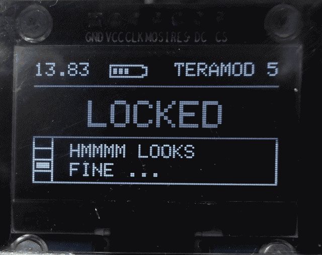
if(DisplayMode == 3)
{
locked = digitalRead(LockPin) ;
display.fillRect(2, 53, 7, 3, WHITE) ;
display.setTextSize(2) ;
if(locked)
{
display.setCursor(29,20) ;
display.print("LOCKED") ;
display.setTextSize(1) ;
display.setCursor(20, 43) ;
display.println("HMMMM LOOKS") ;
display.setCursor(20, 53) ;
display.print("FINE ...") ;
}
else
{
display.setCursor(17,20) ;
display.print("UNLOCKED") ;
display.setTextSize(1) ;
display.setCursor(20, 43) ;
display.println("CHECK REAR BNC") ;
display.setCursor(20, 53) ;
display.print("CONNECTOR ...") ;
}
}
// /////////////////////////////////////////////
// REMOTE / LOCAL
// /////////////////////////////////////////////
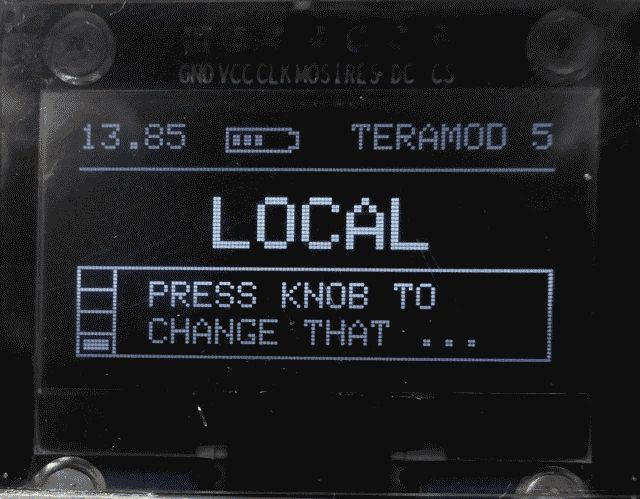
if(DisplayMode == 4)
{
display.fillRect(2, 59, 7, 3, WHITE) ;
display.setCursor(20, 44) ;
display.setTextSize(2) ;
if(IsLocal)
{
display.setCursor(37,20) ;
display.print("LOCAL") ;
}
else
{
display.setCursor(27,20) ;
display.print("REMOTE") ;
}
display.setTextSize(1) ;
display.setCursor(20, 43) ;
display.println("PRESS KNOB TO") ;
display.setCursor(20, 53) ;
display.print("CHANGE THAT ...") ;
}
// BATTERY VOLTAGE INDICATOR
display.setTextSize(1) ;
ReadSupply() ;
display.drawRect(40, 1, 18, 7, WHITE) ;
display.drawRect(58, 2, 2, 5, WHITE) ;
display.fillRect(57, 3, 2, 3, BLACK) ;
if(SupplyVoltage >= 9.0) display.fillRect(42, 3, 2, 3, WHITE) ;
if(SupplyVoltage >= 11.0) display.fillRect(45, 3, 2, 3, WHITE) ;
if(SupplyVoltage >= 13.0) display.fillRect(48, 3, 2, 3, WHITE) ;
if(SupplyVoltage >= 15.0) display.fillRect(51, 3, 2, 3, WHITE) ;
if(SupplyVoltage >= 17.0) display.fillRect(54, 3, 2, 3, WHITE) ;
display.setCursor(0, 0) ;
if(SupplyVoltage < 10.0) display.print(" ") ;
display.print(SupplyVoltage,2) ;
display.display() ;
}
// /////////////////////////////////////////////////////////////////////
// S E T U P
// /////////////////////////////////////////////////////////////////////
void setup()
{
Serial.begin(115200);
pinMode(CS, OUTPUT) ;
pinMode(CLK, OUTPUT) ;
pinMode(DATA, OUTPUT) ;
pinMode(AttPin0, OUTPUT) ;
pinMode(AttPin1, OUTPUT) ;
pinMode(AttPin2, OUTPUT) ;
pinMode(AttPin3, OUTPUT) ;
pinMode(AttPin4, OUTPUT) ;
digitalWrite(CS, HIGH) ;
pinMode(LockPin, INPUT_PULLUP) ;
InitLMX2594() ;
SetAttenuator(AvailPow[Giga] - Level) ;
UpdateFREQ() ;
// YELLOW
attachInterrupt(digitalPinToInterrupt(RotaryEncoder2),
RotaryEncoderISR2, FALLING);
// GREEN
attachInterrupt(digitalPinToInterrupt(RotaryEncoder3),
RotaryEncoderISR3, FALLING);
// INIT OLED
display.begin(SH1106_SWITCHCAPVCC);
// SHOW STARTUP SCREEN
display.clearDisplay();
display.setTextSize(1);
display.setTextColor(WHITE);
display.setCursor(0,0);
display.println("***** TERAMOD *****");
display.drawLine(0, 12, 128, 12, WHITE);
display.setTextSize(1);
display.setCursor(0,21);
display.println("A SHF SYNTHESIZER");
display.setCursor(0,33);
display.println("WITH THE LMX 2594.");
display.setCursor(0,45);
display.println("I.M. CHULALONGKORN.");
display.setCursor(0,57);
display.println("BUILT 23.10.2021");
display.display();
delay(999) ;
UpdateDisplay() ;
}
// /////////////////////////////////////////////////////////////////////
// M A I N
// /////////////////////////////////////////////////////////////////////
void loop()
{
// KEY ROTATED ?
// //////////////////////////////////
if(LEFT)
// //////////////////////////////////
{
if(ShowCursor)
{
CursorPos -= 1 ;
if(CursorPos < 1) CursorPos = 16 ;
if(CursorPos == 11) CursorPos = 10 ;
if(CursorPos == 14) CursorPos = 11 ;
if((CursorPos > 0 ) && (CursorPos < 11)) DisplayMode = 1 ;
if((CursorPos > 10) && (CursorPos < 15)) DisplayMode = 2 ;
if(CursorPos == 15) DisplayMode = 3 ;
if(CursorPos == 16) DisplayMode = 4 ;
// Serial.println(CursorPos,DEC);
}
if(!ShowCursor)
{
switch(CursorPos)
{
case 0 : DecreaseFREQ() ; break ;
case 1 : DecreaseFREQ() ; break ;
case 2 : DecreaseFREQ() ; break ;
case 3 : DecreaseFREQ() ; break ;
case 4 : DecreaseFREQ() ; break ;
case 5 : DecreaseFREQ() ; break ;
case 6 : DecreaseFREQ() ; break ;
case 7 : DecreaseFREQ() ; break ;
case 8 : DecreaseFREQ() ; break ;
case 9 : DecreaseFREQ() ; break ;
case 10: DecreaseFREQ() ; break ;
case 12: DecreaseLEVEL() ; break ;
}
}
delay(159) ;
READY = true ;
LEFT = false ;
RIGHT = false ;
}
// //////////////////////////////////
if(RIGHT)
// //////////////////////////////////
{
if(ShowCursor)
{
CursorPos += 1 ;
if(CursorPos > 16) CursorPos = 1 ;
if(CursorPos == 11) CursorPos = 12 ;
if(CursorPos == 13) CursorPos = 15 ;
if((CursorPos > 0 ) && (CursorPos < 11)) DisplayMode = 1 ;
if((CursorPos > 10) && (CursorPos < 15)) DisplayMode = 2 ;
if(CursorPos == 15) DisplayMode = 3 ;
if(CursorPos == 16) DisplayMode = 4 ;
// Serial.println(CursorPos,DEC);
}
if(!ShowCursor)
{
switch(CursorPos)
{
case 0 : IncreaseFREQ() ; break ;
case 1 : IncreaseFREQ() ; break ;
case 2 : IncreaseFREQ() ; break ;
case 3 : IncreaseFREQ() ; break ;
case 4 : IncreaseFREQ() ; break ;
case 5 : IncreaseFREQ() ; break ;
case 6 : IncreaseFREQ() ; break ;
case 7 : IncreaseFREQ() ; break ;
case 8 : IncreaseFREQ() ; break ;
case 9 : IncreaseFREQ() ; break ;
case 10: IncreaseFREQ() ; break ;
case 12: IncreaseLEVEL() ; break ;
}
}
delay(159) ;
READY = true ;
LEFT = false ;
RIGHT = false ;
}
// //////////////////////////////////
// KEY PRESSED ?
// //////////////////////////////////
{
if(!analogRead(RotaryEncoder1))
{
ShowCursor =!ShowCursor ;
delay(199) ;
}
}
UpdateDisplay() ;
delay(9) ;
}
// /////////////////////////////////////////////////////////////
// INTERRUPT SERVICE ROUTINES
// /////////////////////////////////////////////////////////////
void RotaryEncoderISR2()
{
// YELLOW
if(READY)
{
LEFT = false ;
RIGHT = false ;
byte autre = digitalRead(RotaryEncoder3) ;
if (autre > 0) RIGHT = true ;
if (autre < 1) LEFT = true ;
}
}
void RotaryEncoderISR3()
{
// GREEN
if(READY)
{
LEFT = false ;
RIGHT = false ;
byte autre = digitalRead(RotaryEncoder2) ;
if (autre > 0) LEFT = true ;
if (autre < 1) RIGHT = true ;
}
}
// /////////////////////////////////////////////////////////////
// END OF FILE.
// /////////////////////////////////////////////////////////////
✈ The Menue
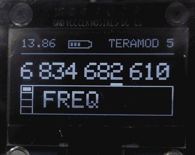
In case the cursor is an underscore, rotating the knob (rotary encoder) will move the cursor through all the decimal places / menues. If you press the knob, the underscore will change into an arrow, indicating that rotating the knob will now change the digit / setting.
✈ Performance
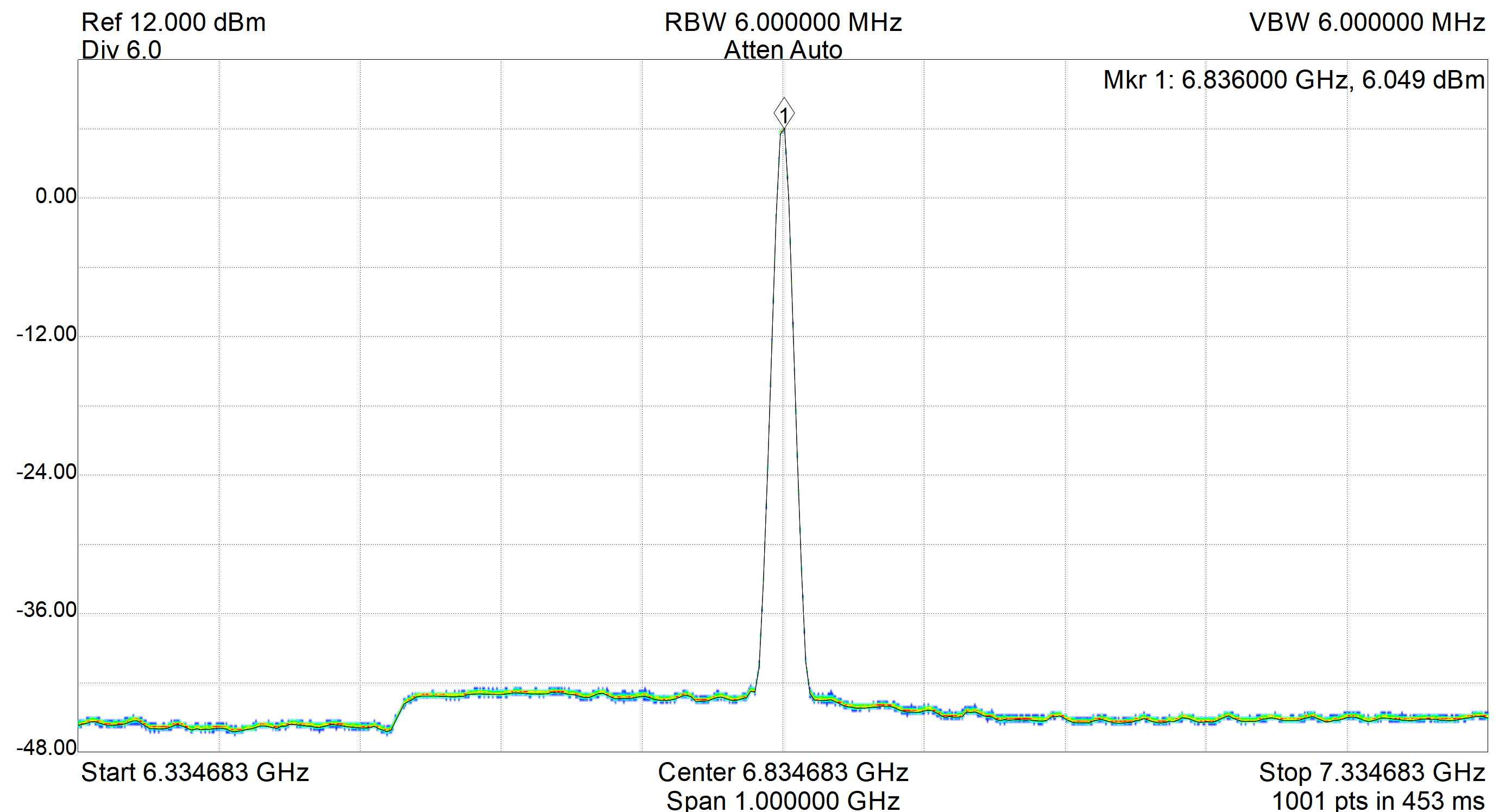
The output at 6.834682610904299 GHz is + 6 dBm (measured with Spike® from Signal Hound)
✈ Reference Clock
The Manual for the Evaluation Board from TI suggests to use a Reference with a Noise level of –139 dBc/Hz at an
Offset of 100 Hz. That is challenging. ($$$). We used a VCXO from Abracon (ABLNO-V-100.000MHZ-T2)
which offers -118 dBc/Hz at 100 Hz Offset. (Digi-key, CHF 12, 2021). Feel free to change that in
your design ...
✈ Hints
The output range spans from 2 GHz up to 15 GHz. This limitation mainly comes from the final amplifier.
We use a HMC462LP5E from Analog Devices (2 GHz to 20 GHz). This one costs about CHF 147.-
(Digi-Key, 07/2019). A similiar device is the HMC460 (DC to 20 GHz), but this one costs CHF 2786.-
(Digi-Key, 07/2019). That is approximately 23 dB more and slightly over budget :-)
FR4 is not nice when operating at frequencies larger than 3 GHz. If you go up in frequency, attenuation increases. Even the coaxial cable introduces 3 dB !!!
FR4 is not nice when operating at frequencies larger than 3 GHz. If you go up in frequency, attenuation increases. Even the coaxial cable introduces 3 dB !!!

✈ Share your thoughts
The webmaster does not read these comments regularely. Urgent questions should be send via email.
Ads or links to completely uncorrelated things will be removed.
|
t1 = 7319 d
t2 = 248 ms |
★ ★ ★ Copyright © 2006 - 2026 by changpuak.ch ★ ★ ★
|

|