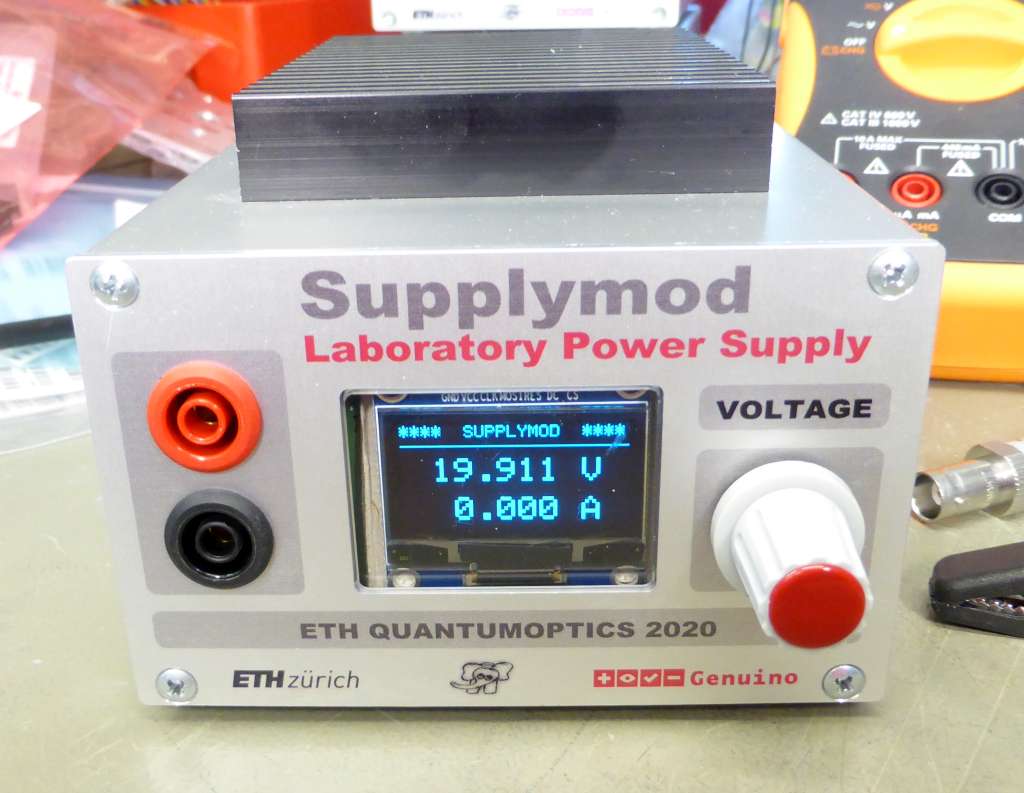
A Voltage Supply, 20V, 2A, controlled by an Arduino Nano
The assembled prototype. And yes, it reaches even 21 Volts, but we like the digit 9 ...
Do not expect Specifcations as known from a Rohde & Schwarz™ Power Supply.
Instead, this Project serves to learn about Serial Communication with e.g. a Python GUI.
Even so it has a good Long-Term Stability, the absolut value of the output voltage mayst
be slightly off by some Millivolts. And the Current Limiting is done by Software ...
✈ Motivation
You can never have enough Power Supplies. Students often order cheap things from
the land of the rising sun. But they do fail soon, because students are shy and order
based on (lowest) price. Therefore we developped
an instructeable thing which shall last longer. Much longer. You even can control it with a
Python GUI. (As I have now a lot of time developping Software :-)
✈ The Design
To make things easy, we used a EPS-65S-24 (24 V, 2.7 A Switching Power Supply from MEAN WELL).
It has an expected lifetime (MTBF) of 959'100 hrs (> 100 years) and an efficiecy of
90 %. It delivers 24 V with a ripple of 240 mVpp. By that, we get rid of a
huge transformer. (And have a relatively smooth input voltage).
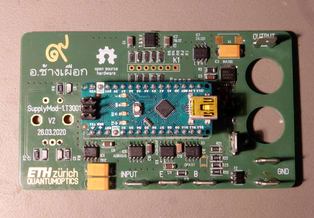
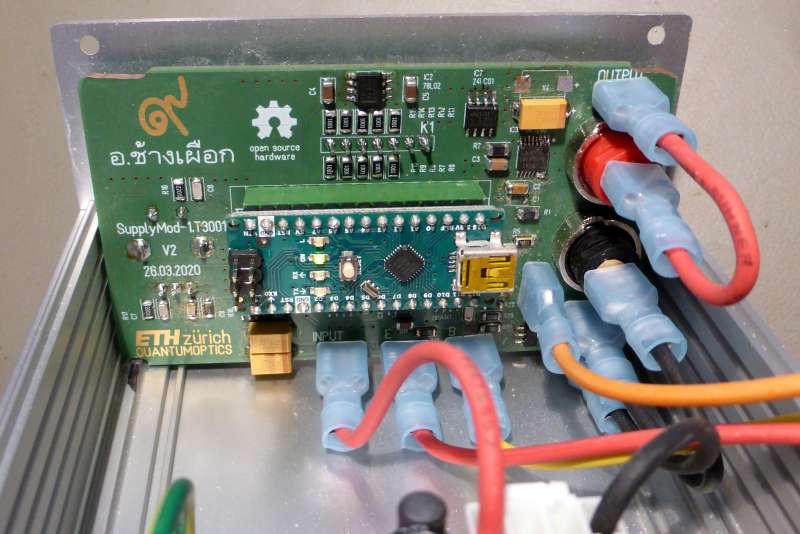
The workhorse. Picture courtesy of Distrelec.The brain. Arduino Nano with some 'co-workers'
The Block Diagram of the regulation looks like this :
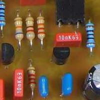
The Voltage is linear regulated with an TIP3055 (NPN-Pass-Transistor, complementary of TIP2955)
which is mounted on a
heatsink (1.8 K/W). As it has good thermal contact to the case, we mayst add the case to the surface
area of it.
The Setpoint is set with a Rotary Encoder using Interrupt Service Routines (connected to Pin2 and Pin3).
We use an ADR4540 (Ultralow Noise, High Accuracy
Voltage Reference) to produce a stable 4.096 V Reference Voltage. This Voltage is then fed
to an AD8400AR (1 Channel Digital Potentiometer). This Potentiometer has 256 steps.
Therefore we can set the Output Voltage in 6.25 * 4.096 / 256 = 100 mV Steps. This may look poor,
but in practice it deems sufficient.
A 24LC01 (1K I2C™ Serial EEPROM) is used to store the output voltage, so that when you
switch it on again, it will produce the same Output Voltage. Pressing the knob will save the
current Voltage Setpoint to the Eeprom.
The Current Limiting is done by the Arduino. As it is always aware of the Power delivered to
the Load (INA260), it can reduce the Voltage, when an Over Power Situation occurs. That's the Plan.
Be aware, that the Arduino/Genuino™ Nano uses the (hard to find) Mini USB Type B connector.
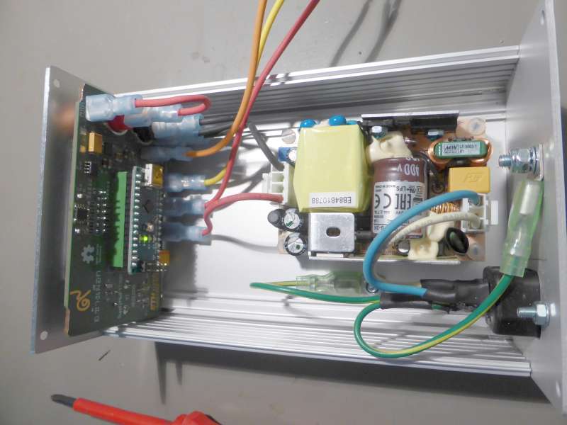
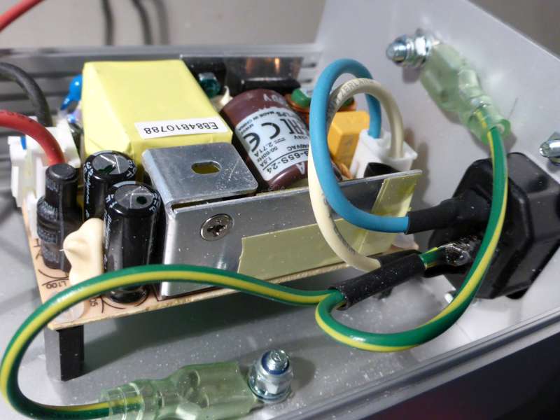
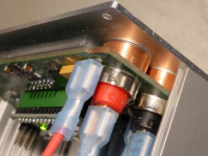
Some impressions from 'inside' :
View inside ... not much to be seen :-)The "Pre-Regulator" has a built-in fuse
7 mm Copper Spacer align the PCBFrontpanel, which actually does most of the job
✈ The Heatsink • Safe Operating Area
The Heatsink was chosen because of it's form-factor. It is a SK 81 75 SA from Fischer Elektronik.
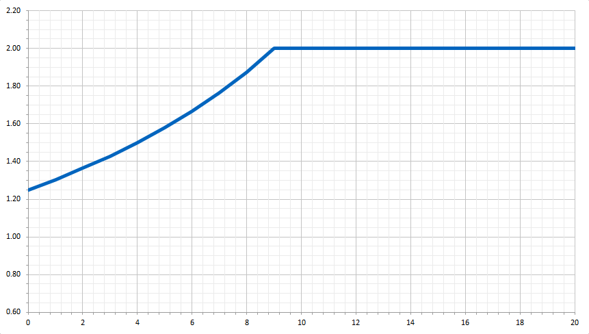
It has a thermal resistance of 2.5 K/W. With it, we can dissipate about 30 Watts. If you do the
math, a curve similiar to the one below shows, that the dangerous zone is the voltage range up to
approx. 9 Volts. In that region, the current must be lowered in order not to self-destruct.
Maximum permissible Current as a function of Output Voltage, aka Safe Operating Area
✈ Downloads
✈ Test Sketch for Arduino/Genuino Nano
Double click on code to select ...
/* //////////////////////////////////////////////////////////////////

  ARDUINO/Genuino Project "SUPPLYMOD", a 20V, 2A Power Supply
  https://www.changpuak.ch/electronics/Arduino-SupplyMod.php
  Software Version 1.0
  19.05.2020 by ALEXANDER SSE FRANK

  USES LIBRARY FROM Matthew Brush mbrush@codebrainz.ca, (C) 2018
  https://github.com/codebrainz/ina260

////////////////////////////////////////////////////////////////// */

#include <Wire.h>
#include <Adafruit_GFX.h>
#include <Adafruit_SH1106.h>
#include <INA260.h>
static INA260 ina260(0);
double value = 0.0 ;


// DISPLAY

#define OLED_MOSI  A2
#define OLED_CLK   A1
#define OLED_DC    5
#define OLED_CS    4
#define OLED_RESET A3

// DAC

#define DAC_CS     7
#define DAC_DATA   6
#define DAC_CLCK   8
int DAC_VAL = 205 ;
int MAX_DAC_VAL = 210 ;   // 21.0 Volts+

// ROTARY ENCODER
const int RotaryEncoder1 = A0 ;   // PRESSED
const int RotaryEncoder2 = 2 ;
const int RotaryEncoder3 = 3 ;
volatile boolean LEFT = false ;
volatile boolean RIGHT = false ;
volatile boolean READY = true ;

// SERIAL COMMUNICATION
byte B[20] ;                 // holds User Input from Serial
int pointer = 0 ;

// EEPROM
#define EEPROM_24C01_I2CADDR 0x50

Adafruit_SH1106 display(OLED_MOSI, OLED_CLK, OLED_DC, OLED_RESET, OLED_CS);

#if (SH1106_LCDHEIGHT != 64)
#error("Height incorrect, please fix Adafruit_SH1106.h!");
#endif


float Volt = 20.000 ;                     // UNIT IS V
float Current = 1.601 ;                   // UNIT IS A
float CALVolt = 0.000 ;
float CALCurrent = 0.002 ;
boolean OutputON = true ;
float MAXCurent = 2.1 ;


// /////////////////////////////////////////////////////////////
// EEPROM ROUTINES
// /////////////////////////////////////////////////////////////


void Save()
{
  Wire.beginTransmission(EEPROM_24C01_I2CADDR);
  Wire.write(0x00);
  Wire.write(DAC_VAL);
  Wire.endTransmission();
}

void Load()
{
  Wire.beginTransmission(EEPROM_24C01_I2CADDR);
  Wire.write(0x00);
  Wire.endTransmission();
  Wire.requestFrom(EEPROM_24C01_I2CADDR,1);
  delay(1) ;
  if (Wire.available()) DAC_VAL = Wire.read();
  if (DAC_VAL == 0xFF) DAC_VAL = 0 ;
}


// /////////////////////////////////////////////////////////////
// Serial Communication Routines
// /////////////////////////////////////////////////////////////


void ShowInputBuffer()
{
  // FOR DEBUG REASON ONLY :-)
  for (int i = 0; i < 10; i++)
  {
    Serial.print("B[") ;
    Serial.print(i, DEC) ;
    Serial.print("] = ") ;
    Serial.println(B[i]) ;
  }
}

void FlushInputBuffer()
{
  while (Serial.available())
  {
    B[19] = Serial.read() ;
  }
  for (int i = 0; i < 20; i++) B[i] = 32 ;
}


void CheckForSerialInput()
{
  if (Serial.available())
  {
    B[pointer] = Serial.read() ;
    pointer += 1 ;
    if (pointer > 19) pointer = 0 ; // EMERGENCY BREAK
  }
}


void EvaluateSerialInput()
{
  // *IDN?
  if ((B[0]==42)&&(B[1]==73)&&(B[2]==68)&&(B[3]==78)&&(B[4]==63))
  {
    Serial.println("Supplymod V2.0 by Changpuak.ch (C) 07/2020") ;
    FlushInputBuffer() ;
    pointer = 0 ;
  }
  // IOUT?
  else if ((B[0]==73)&&(B[1]==79)&&(B[2]==85)&&(B[3]==84)&&(B[4]==63))
  {
    Serial.print(Current, 4) ;
    Serial.println(" A") ;
    FlushInputBuffer() ;
    pointer = 0 ;
  }
  // POUT?
  else if ((B[0]==80)&&(B[1]==79)&&(B[2]==85)&&(B[3]==84)&&(B[4]==63))
  {
    Serial.print(Current*Volt, 4) ;
    Serial.println(" W") ;
    FlushInputBuffer() ;
    pointer = 0 ;
  }
  // VOUT?
  else if ((B[0]==86)&&(B[1]==79)&&(B[2]==85)&&(B[3]==84)&&(B[4]==63))
  {
    Serial.print(Volt, 4) ;
    Serial.println(" V") ;
    FlushInputBuffer() ;
    pointer = 0 ;
  }
  // SAVE!
  else if ((B[0]==83)&&(B[1]==65)&&(B[2]==86)&&(B[3]==69)&&(B[4]==33))
  {
    Save() ;
    Serial.println("OK") ;
    FlushInputBuffer() ;
    pointer = 0 ;
  }
  // ISETx.xxx

  // VSETxx.xx
  else if ((B[0]==86)&&(B[1]==83)&&(B[2]==69)&&(B[3]==84)&&(B[4]==58))
  {
  // VOLTAGE BELOW 10.0 VOLTS
  // CHECK IF THERE ARE ENOUGH DIGITS
  if ((B[5]>47)&&(B[6]==46)&&(B[7]>47))
  {
    // CHECK IF THERE ARE DIGITS
    if ((B[5]<58)&&(B[7]<58))
    {
      DAC_VAL = 10*(B[5]-48)+(B[7]-48) ;
      UpDateDac() ;
      Serial.println("OK") ;
      FlushInputBuffer() ;
      pointer = 0 ;
    }
  }
  // VOLTAGE ABOVE 9.9999 VOLTS
  // CHECK IF THERE ARE ENOUGH DIGITS
  if ((B[5]>47)&&(B[6]>47)&&(B[7]==46)&&(B[8]>47))
  {
    // CHECK IF THERE ARE DIGITS
    if ((B[5]<58)&&(B[6]<58)&&(B[8]<58))
    {
    DAC_VAL = 100*(B[5]-48)+10*(B[6]-48)+(B[8]-48) ;
    UpDateDac() ;
    Serial.println("OK") ;
    FlushInputBuffer() ;
    pointer = 0 ;
    }
  }
  }
  else
  {
  // THROW AWAY GARBAGE FROM SERIAL INPUT
  if((B[0]!=42)&&(B[0]!=73)&&(B[0]!=86)&&(B[0]!=32)&&(B[0]!=80)&&(B[0]!=83))
    {
    Serial.println("SYNTAX ERROR. UNKNOWN COMMAND.") ;
    FlushInputBuffer() ;
    pointer = 0 ;
    }
  }
}


// /////////////////////////////////////////////////////////////////////
// SUBROUTINES DISPLAY.
// /////////////////////////////////////////////////////////////////////


void DisplayValue(float WERT)
{
  if (abs(WERT) < 10.000) display.print(" ") ;
  display.print(WERT, 3) ;
}


void UpDateDisplay()
{
  display.clearDisplay();
  display.setTextSize(1);
  display.setTextColor(WHITE);
  display.setCursor(0, 0);
  display.println("****  SUPPLYMOD  ****");
  display.drawLine(0, 12, 128, 12, WHITE);
  display.setTextSize(2) ;

  if (OutputON)
  {
    // VOLTAGE
    display.setCursor(18, 20) ;
    DisplayValue(Volt) ;
    display.print(" V") ;
    // CURRENT
    display.setCursor(18, 44) ;
    DisplayValue(Current) ;
    display.print(" A") ;
  }
  else
  {
    display.setCursor(4, 32) ;
    display.print("OUTPUT OFF") ;
  }

  display.display() ;
}


// /////////////////////////////////////////////////////////////////////
// SUBROUTINES DAC
// /////////////////////////////////////////////////////////////////////


void UpDateDac()
{
  // CHECK FOR OVERFLOW
  if(DAC_VAL > MAX_DAC_VAL) DAC_VAL = MAX_DAC_VAL ;
  // Addr = 00
  digitalWrite(DAC_DATA, LOW) ;
  digitalWrite(DAC_CS, LOW) ;
  // ADDRESS
  digitalWrite(DAC_CLCK, HIGH) ; digitalWrite(DAC_CLCK, LOW) ;
  digitalWrite(DAC_CLCK, HIGH) ; digitalWrite(DAC_CLCK, LOW) ;
  // DATA
  shiftOut(DAC_DATA, DAC_CLCK, MSBFIRST, DAC_VAL) ;
  digitalWrite(DAC_CS, HIGH) ;
}


// /////////////////////////////////////////////////////////////////////
// SUBROUTINES INA 260
// /////////////////////////////////////////////////////////////////////


void UpDateINA260()
{
  ina260.readCurrentRegisterInAmps(value) ;
  Current = abs(value + CALCurrent) ;
  // Current = fabs(value  +  CALCurrent)   ;
  ina260.readBusVoltageRegisterInVolts(value) ;
  Volt = value + CALVolt ;
}


// /////////////////////////////////////////////////////////////////////
// S E T U P
// /////////////////////////////////////////////////////////////////////


void setup()
{
  Serial.begin(115200) ;

  Wire.begin() ;

  // DAC PINS
  pinMode(DAC_CS, OUTPUT );
  pinMode(DAC_DATA, OUTPUT );
  pinMode(DAC_CLCK, OUTPUT );

  // INIT OLED
  display.begin(SH1106_SWITCHCAPVCC);

  // SHOW STARTUP SCREEN
  display.clearDisplay();
  display.setTextSize(1);
  display.setTextColor(WHITE);
  display.setCursor(0, 0);
  display.println("****  SUPPLYMOD  ****");
  display.drawLine(0, 12, 128, 12, WHITE);
  display.setTextSize(1);
  display.setCursor(0, 21);
  display.println("20V, 2A POWER SUPPLY");
  display.setCursor(0, 33);
  display.println("FOR LABORATORY USE.");
  display.setCursor(0, 45);
  display.println("(C) ETH QUANTUMOPTICS");
  display.setCursor(0, 57);
  display.println("BUILT 25.07.2020");
  display.display();
  delay(999) ;

  ina260.begin() ;

  /*
  AVG_1 = 0b000,
  AVG_4 = 0b001,
  AVG_16 = 0b010,
  AVG_64 = 0b011,
  AVG_128 = 0b100,
  AVG_256 = 0b101,
  AVG_512 = 0b110,
  AVG_1024 = 0b111,
  VBUSCT_140US = 0b000,
  VBUSCT_204US = 0b001,
  VBUSCT_332US = 0b010,
  VBUSCT_588US = 0b011,
  VBUSCT_1_1MS = 0b100,
  VBUSCT_2_116MS = 0b101,
  VBUSCT_4_156MS = 0b110,
  VBUSCT_8_244MS = 0b0111,
  ISHCT_140US = 0b000,
  ISHCT_204US = 0b001,
  ISHCT_332US = 0b010,
  ISHCT_588US = 0b011,
  ISHCT_1_1MS = 0b100,
  ISHCT_2_116MS = 0b101,
  ISHCT_4_156MS = 0b110,
  ISHCT_8_244MS = 0b111,
  */

  INA260::ConfigurationRegister configReg = {0};
  configReg.avg = INA260::AVG_16 ;
  configReg.vbusct = INA260::VBUSCT_2_116MS ;
  configReg.ishct = INA260::ISHCT_8_244MS ;
  configReg.mode = INA260::MODE_ISH_VBUS_CONTINUOUS ;
  ina260.writeConfigurationRegister(configReg) ;


  delay(999) ;

  Load() ;
  UpDateDac() ;

  FlushInputBuffer() ;

  delay(999) ;

  pinMode(RotaryEncoder1, INPUT_PULLUP);
  pinMode(RotaryEncoder2, INPUT_PULLUP);
  pinMode(RotaryEncoder3, INPUT_PULLUP);
  // YELLOW
  attachInterrupt(digitalPinToInterrupt(RotaryEncoder2), RotaryEncoderISR2, FALLING);
  // GREEN
  attachInterrupt(digitalPinToInterrupt(RotaryEncoder3), RotaryEncoderISR3, FALLING);

  Serial.println("Supplymod V2.0 by Changpuak.ch (C) 07/2020") ;
  UpDateINA260() ;
  Serial.print("Voltage : ") ;
  Serial.print(Volt, 4) ;
  Serial.println(" V") ;
  Serial.print("Current : ") ;
  Serial.print(Current, 4) ;
  Serial.println(" A") ;
  Serial.println("Device ready.\n") ;

  delay(3000);
}


// /////////////////////////////////////////////////////////////////////
// M A I N L O O P
// /////////////////////////////////////////////////////////////////////


void loop()
{
  // EVALUATE ROTARY ENCODER
  if (LEFT)
  {
    READY = false ;
    DAC_VAL -= 1 ;
    if (DAC_VAL < 0) DAC_VAL = 0 ;
    UpDateDac() ;
    LEFT = false ;
    RIGHT = false ;
    READY = false ;
    delay(149) ;
    READY = true ;
  }

  if (RIGHT)
  {
    READY = false ;
    DAC_VAL += 1 ;
    if (DAC_VAL > MAX_DAC_VAL) DAC_VAL = MAX_DAC_VAL ;
    UpDateDac() ;
    LEFT = false ;
    RIGHT = false ;
    READY = false ;
    delay(149) ;
    READY = true ;
  }
  if(Current >= MAXCurent)
  {
    DAC_VAL -= 1 ;
    if (DAC_VAL < 0) DAC_VAL = 0 ;
    UpDateDac() ;
  }
  UpDateINA260() ;
  UpDateDisplay() ;
  // Check Serial Input
  CheckForSerialInput() ;
  EvaluateSerialInput() ;
  // SAVE VALUE WHEN KNOB IS PRESSED
  if(digitalRead(RotaryEncoder1)==0) Save() ;

  // Serial.println(Volt,4);
}


// /////////////////////////////////////////////////////////////////////
// INTERRUPT SERVICE ROUTINES
// /////////////////////////////////////////////////////////////////////


void RotaryEncoderISR3()
{
  // YELLOW
  if(READY)
  {
  LEFT = false ;
  RIGHT = false ;
  byte autre = digitalRead(RotaryEncoder3) ;
  if (autre > 0) LEFT = true ;
  if (autre < 1) RIGHT = true ;
  }
}

void RotaryEncoderISR2()
{
  // GREEN
  if(READY)
  {
  LEFT = false ;
  RIGHT = false ;
  byte autre = digitalRead(RotaryEncoder2) ;
  if (autre > 0) RIGHT = true ;
  if (autre < 1) LEFT = true ;
  }
}


// /////////////////////////////////////////////////////////////
// END OF FILE.
// /////////////////////////////////////////////////////////////
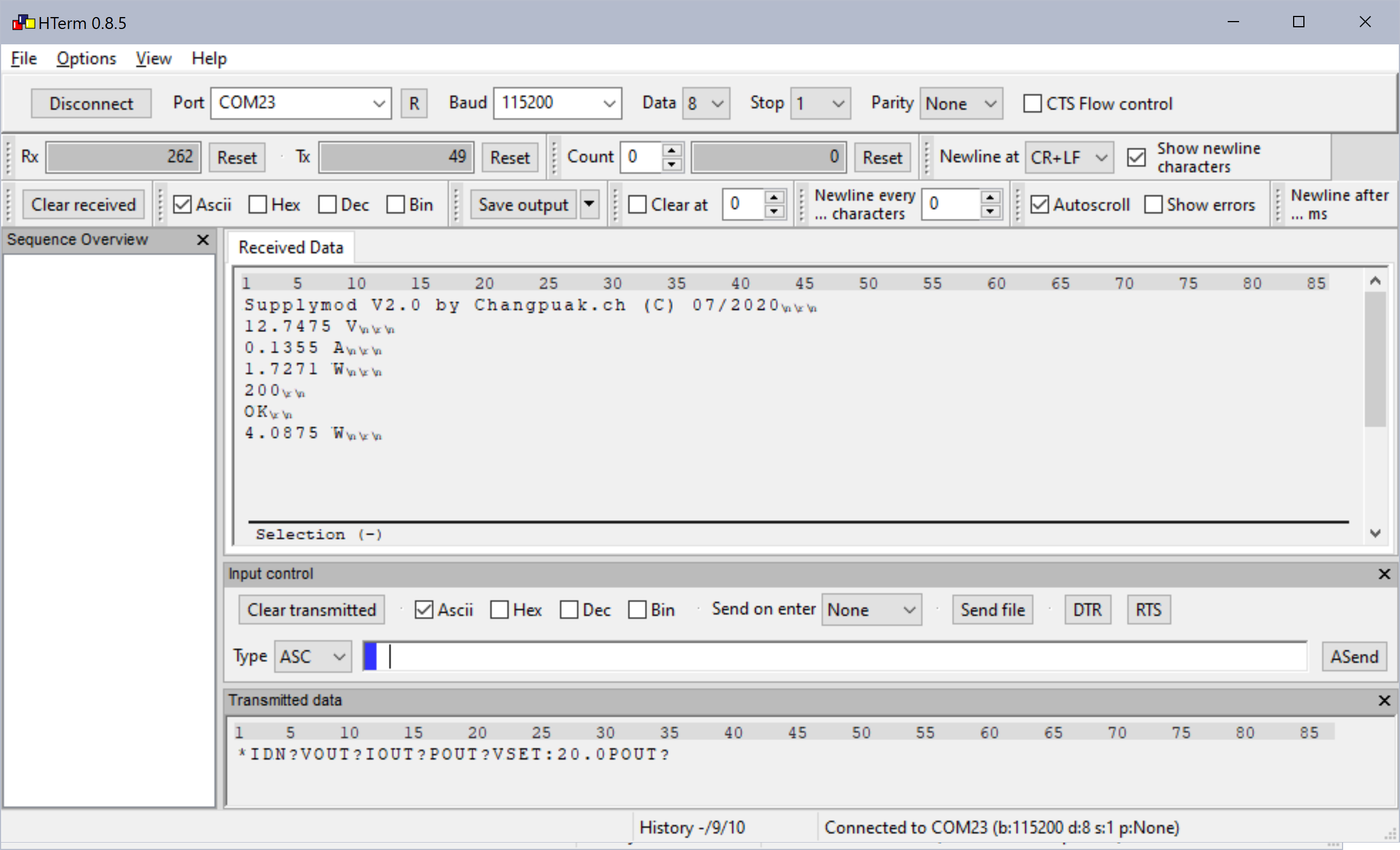
✈ Remote Control of the Supplymod
COM SETTINGS :
Set up the COM port inside the PC according to the following list.
• Baud rate: 115200
• Parity bit: None
• Data bit: 8
• Stop bit: 1
• Data flow control: None
COMMAND SYNTAX : VSET:xx.x OR VSET:x.x
Description: Sets the output voltage.
Example VSET:16.5
Sets the voltage to 16.5V
Returns O.K.
IOUT?
Description:Returns the actual output current.
Example IOUT?
Returns the output current.
VOUT?
Description:Returns the actual output voltage.
Example VOUT?
Returns the output voltage.
POUT?
Description:Returns the actual output power.
Example POUT?
Returns the output power delivered to the load.
*IDN?
Description:Returns the Supplymod identification.
Example *IDN?
Returns Supplymod V2.0 by Changpuak.ch (C) 07/2020
SAVE!
Description:Stores the actual Voltage into the Eeprom
Example SAVE!
Returns O.K.
Remote Control with e.g. HTerm 0.8.5 from Tobias Hammer
✈ Performance
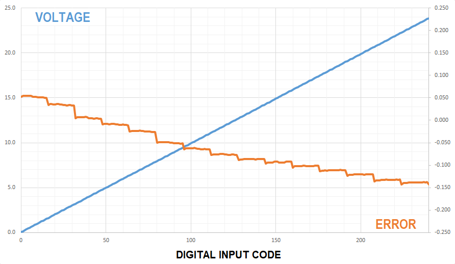
Ramping up the AD8400 Potentiometer
The line is strictly monotonic rising and offers no surprises. Even with a "low-cost 8 Bit Potentiometer", one can build a useable D/A Converter.
We used the 10 kΩ version here. (The output of the Power Supply was unloaded, but the voltage does not change if loaded.). Also visible is the lower limit
of approx. 53 mV - much better than a LM317 approach. The error is slightly over the
"± 1 LSB" specifications from AD, especially at the upper end.
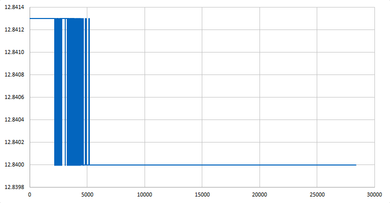
Long Term Drift
We see, that after about 5000 s, the voltage remains constant. Obviously this is a warm-up
issue. As the absolut drift is below 2 mV, we may neglect that. Measured with the built-in
INA260.
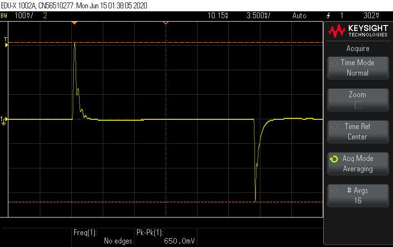
Response to Load Changes
The Power Supply needs about 2 ms to regulate for jumps in load changes. This is mainly caused
by the relatively large capacitor C12 (10nF).
✈ Credits
We would like to thank the team of TARGET 3001!
as well as the team of Beta Layout
for ultrafast and very professional support.
✈ Errata
Luca informed me, that the abs() value
of a double does not work. Please note his solution of using fabs() in line 291. This mayst depend
on the compiler you use.
Grazie mille !
✈ Share your thoughts
The webmaster does not read these comments regularely. Urgent questions should be send via email.
Ads or links to completely uncorrelated things will be removed.
 ช้างเผือก