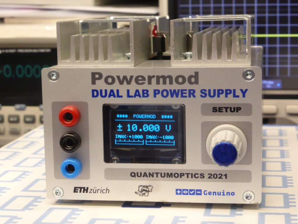
A Dual Voltage Supply, ±15 V, 999 mA, controlled by an Arduino
The assembled prototype. True zero to ±15 V in 100 mV steps.
✈ The Design
The Design is actually very classic. The only new thing here is the use of four ADG1412
(1.5 Ω On Resistance, ±15 V, iCMOS, Quad SPST Switch). They switch precision
resistors in / out a ladder of precision resistors defining the output voltage of a LM317
and LM337. And yes : the reference node is not GND, but instead an offset voltage of ±1.4 V,
generated by another pair of LM317/LM337. By that we can reach true zero volts at the output.
Those switches are controlled by
two 74HC595 (8-bit serial-in/serial or parallel-out shift register with output latches).
A good old friend, not only in the arduino community :-)
For potential-free current measurement, we used twice the ACS70331EOLCTR-005B3
(GMR-Based Current Sensor IC). Unfortunately the smaller (more precise) types are
currently unavailable.
Last but not least, we use an Arduino / Genuino Nano Every to take care of that
housekeeping stuff, as well as the communication to the outer world.
And yes : The two Voltage Setpoints can be programmed individually. The solution presented
here does not make use of that. You always get a symmetrical output. We also have heard,
that other power supplies can be programmed in 1 mV steps. We don't need that.
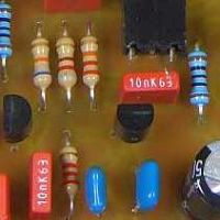
✈ The R-2R Ladder Network
As we have chosen the Reference Resistor to be 250 Ω (those 4 x 1 kΩ in the bottom of the
picture), we get an adjustement current of exactly 5 mA.
We have also chosen, that the LSB shall correspond to a Voltage of 100 mV. Using the 8 Bits
from the 74HC595, we can step up to 25.5 Volts (theoretically) in steps of 100 mV.
As we do start at - 1.3 V to achieve true zero at the output, the theoretical limit is only
24.2 V. (The practical limit is given by the Supply voltage of the switch).
It is possible to create the necessary Resistors by using only 2 resistors of the E24 Series. With
this
cool tool, we found the following combinations :
VOLTAGE/BIT
RESISTANCE
LINEAR COMBINATION
100 mV, LSB
20 Ω
10 Ω + 10 Ω
200 mV
40 Ω
20 Ω + 20 Ω
400 mV
80 Ω
12 Ω + 68 Ω
800 mV
160 Ω
10 Ω + 150 Ω
1.6 V
320 Ω
20 Ω + 300 Ω
3.2 V
640 Ω
20 Ω + 620 Ω
6.4 V
1280 Ω
180 Ω + 1.1 kΩ
12.8 V, MSB
2560 Ω
560 Ω + 2 kΩ
And yes : The Resistance of the Switch of 1.5 Ω has been neglected here.
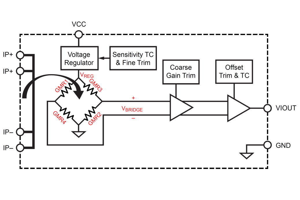
✈ What's all this giant magneto-resistive stuff anyhow ?
"Giant magneto-resistive elements (GMR) measure the current flowing through the conductor
indirectly by measuring the field produced by the current. These elements operate differently
than Hall-effect sensors. GMR elements are essentially resistors which change resistance with
applied field."
"The die sits above the primary current path
such that magnetic field is produced in plane with the GMR elements
on the die. GMR elements 1 and 2 sense field in the +X
direction for positive IP current flow, and GMR elements 3 and 4
sense field in the –X direction for positive IP current flow. This
enables differential measurement of the current and rejection of
external stray fields.
The four GMR elements are arranged in a Wheatstone bridge
configuration as shown in Figure 3 such that the output of the
bridge is proportional to the differential field sensed by the four
elements, rejecting common fields." Says the
datasheet.
Figure 2 and 3 courtesy of ALLEGRO microsystems. Text courtesy of ALLEGRO microsystems.
✈ Downloads
✈ Test Sketch for Arduino/Genuino Nano
Double click on code to select ...
/* //////////////////////////////////////////////////////////////////

  ARDUINO/Genuino Project "POWERMOD", yet another Power Supply
  with the LM317 and LM337 ... but this one is programmeable :-)
  https://www.changpuak.ch/electronics/Arduino-Powermod.php
  Software Version 1.0
  20.05.2021 by ALEXANDER SSE FRANK

////////////////////////////////////////////////////////////////// */

#include <Wire.h>
#include <Adafruit_GFX.h>
#include <Adafruit_SH1106.h>


// DISPLAY
#define OLED_MOSI  A2
#define OLED_CLK   A3
#define OLED_DC    A0
#define OLED_CS    13
#define OLED_RESET A1


Adafruit_SH1106 display(OLED_MOSI, OLED_CLK, OLED_DC, OLED_RESET, OLED_CS);

#if (SH1106_LCDHEIGHT != 64)
#error("Height incorrect, please fix Adafruit_SH1106.h!");
#endif


// ROTARY ENCODER
const int RotaryEncoder1 = 4 ;   // PRESSED
const int RotaryEncoder2 = 2 ;
const int RotaryEncoder3 = 3 ;
volatile boolean LEFT = false ;
volatile boolean RIGHT = false ;
volatile boolean READY = true ;


// /////////////////////////////////////////////////////////////
// SUBROUTINES CURRENT MEASUREMENT WITH ACS70331EOLCTR-005B3
// /////////////////////////////////////////////////////////////

// MAX READING = 1023
// MAX VALUE +/- 5 A
// SENSITIVITY 200 mV / A = 0.2 V * 1023 / 3.3 V = 62 / 1000 mA
// Zero Current Output Voltage : 1.5 V Datasheet p. 10 (SOIC)
// Offset = 1.5 V * 1023 / 3.3 V = 465
const int IposPin = A6 ;
const int InegPin = A7 ;
const int IposOffset = 459 ;  // 459 is a good value
const int InegOffset = 465 ;  // 465 is a good value
const float IposGain = 14.2 ;
const float InegGain = 15.0 ;
const int IAvg = 301 ;
int Ipos = 0 ; // x 1 mA
int Ineg = 0 ;
const int Iposmax = 1000 ;
const int Inegmax = 1000 ;


void UpdateCurrent()
{
  long SumP = 0 ;
  long SumN = 0 ;
  for(int i = 0 ; i < IAvg ; i++)
  {
    SumP += ( analogRead(IposPin) - IposOffset ) ;
    SumN += ( analogRead(InegPin) - InegOffset ) ;
    delay(1) ;
  }
  Ipos = abs(IposGain * SumP / IAvg) ;
  Ineg = abs(InegGain * SumN / IAvg) ;

  Serial.print(Ipos,DEC) ; Serial.print(",") ;
  Serial.println(Ineg,DEC) ;
}


// /////////////////////////////////////////////////////////////
// SUBROUTINES VOLTAGE SETTING
// /////////////////////////////////////////////////////////////

float Volt = 3.3 ;
const float VoltMax = 15.20 ;
const float VoltMin = 0.0 ;
// GLEICHLAUF
byte VoltPosOffset = 0 ;
byte VoltNegOffset = 2 ;

const int DataP = 8 ;
const int ClockP = 9 ;
const int LatchP = 10 ;
const int DataN = 5 ;
const int ClockN = 6 ;
const int LatchN = 7 ;

void UpdateVoltage()
{
  byte DataByte = 0xFF - (int)( 10.0 * Volt + 0.5 ) ;

  // POSITIVE REGULATOR LM317
  digitalWrite(LatchP, LOW);
  shiftOut(DataP, ClockP, MSBFIRST, DataByte+VoltPosOffset) ;
  digitalWrite(LatchP, HIGH);

  // NEGATIVE REGULATOR LM337
  digitalWrite(LatchN, LOW);
  shiftOut(DataN, ClockN, MSBFIRST, DataByte+VoltNegOffset) ;
  digitalWrite(LatchN, HIGH);
}


// /////////////////////////////////////////////////////////////
// SUBROUTINES DISPLAY.
// /////////////////////////////////////////////////////////////

int MAX_BAR_LENGTH = 60 ;
int MIN_BAR_LENGTH = 0 ;

void BAR_POS(float value)
{
  int BAR_LENGTH = MAX_BAR_LENGTH * value / Iposmax ;
  if (BAR_LENGTH > MAX_BAR_LENGTH) BAR_LENGTH = MAX_BAR_LENGTH ;
  if (BAR_LENGTH < MIN_BAR_LENGTH) BAR_LENGTH = MIN_BAR_LENGTH ;
  display.fillRect(0, 58, BAR_LENGTH, 6, WHITE);
  display.fillRect(BAR_LENGTH+1, 58, MAX_BAR_LENGTH-BAR_LENGTH-2, 6, BLACK);
  display.drawRect(0, 57, 61, 7, WHITE);
}


void BAR_NEG(float value)
{
  int BAR_LENGTH = MAX_BAR_LENGTH * value / Inegmax ;
  if (BAR_LENGTH > MAX_BAR_LENGTH) BAR_LENGTH = MAX_BAR_LENGTH ;
  if (BAR_LENGTH < MIN_BAR_LENGTH) BAR_LENGTH = MIN_BAR_LENGTH ;
  display.fillRect(66, 58, BAR_LENGTH, 6, WHITE);
  display.fillRect(66+BAR_LENGTH+1, 58, MAX_BAR_LENGTH-BAR_LENGTH-2, 6, BLACK);
  display.drawRect(66, 57, 61, 7, WHITE);
}


void UpdateDisplay()
{
  display.clearDisplay();
  display.setTextColor(WHITE) ;
  display.setTextSize(1) ;
  display.setCursor(4,0) ;
  display.print("****  POWERMOD  ****") ;
  // LINE
  display.drawLine(0, 12, 128, 12, WHITE) ;
  // VOLTAGE
  display.setTextSize(2) ;
  display.setCursor(5,19) ; display.print("+") ;
  display.setCursor(5,27) ; display.print("-") ;
  display.setCursor(25,21) ;
  if(Volt < 9.99) display.print(" ") ;
  display.print(Volt,3) ;
  display.print(" V") ;
  // DRAW TICKS CURRENT BAR
  display.setTextSize(1) ;
  display.setCursor(0,35) ;
  for (int i=0; i<=6; i++)
  {
    display.drawLine(i*10, 54, i*10, 58, WHITE) ;
  }
  for (int i=0; i<=6; i++)
  {
    display.drawLine(i*10+66, 54, i*10+66, 58, WHITE) ;
  }
  display.setTextSize(1) ;
  display.setCursor(0,44) ;
  display.print("IMAX:+") ; display.print(Iposmax,DEC) ;
  display.setCursor(66,44) ;
  display.print("IMAX:-") ; display.print(Inegmax,DEC) ;

  BAR_POS(Ipos) ;
  BAR_NEG(Ineg) ;
  display.display() ;
}

// /////////////////////////////////////////////////////////////
// SUBROUTINES SERIAL
// /////////////////////////////////////////////////////////////

String incoming = "nil";

void EvalSerial()
{
  int longines = 0 ;
  boolean handled = false ;
  if (Serial.available() > 0)
  {
    incoming = Serial.readString();

    // SET VOLTAGE
    if (incoming.startsWith("VSET:"))
    {
    longines = incoming.length() ;
    incoming = incoming.substring(5,longines) ;
    Volt = incoming.toFloat() ;
    if(Volt > VoltMax) Volt = VoltMax ;
    if(Volt < VoltMin) Volt = VoltMin ;
    Volt = ((unsigned long)(Volt * 10.0)) / 10.0 ;
    Serial.println("O.K.");
    handled = true ;
    }

    // ASK FOR CURRENT
    if (incoming.startsWith("IOUT?"))
    {
    UpdateCurrent() ;
    Serial.print("CURRENT : +") ;
    Serial.print(Ipos,DEC) ; Serial.print(" mA, -") ;
    Serial.print(Ineg,DEC) ; Serial.println(" mA.\n") ;
    handled = true ;
    }

    // WHOIS
    if (incoming.startsWith("*IDN?"))
    {
    Serial.println("POWERMOD 2.0 BY CHANGPUAK.CH\n") ;
    Serial.println("SYSTEM READY.") ;
    Serial.print("VOLTAGE : ") ;
    Serial.print(Volt,3) ; Serial.println(" V") ;
    Serial.print("CURRENT : +") ;
    Serial.print(Ipos,DEC) ; Serial.print(" mA, -") ;
    Serial.print(Ineg,DEC) ; Serial.println(" mA.\n") ;
    handled = true ;
    }

    // SAVE VALUE TO EEPROM
    if (incoming.startsWith("SAVE!"))
    {
    Save() ;
    Serial.println("O.K.") ;
    handled = true ;
    }

    // NO SPEAK AMERICANO
    if (!handled)
    {
    Serial.println("OOOOPS - SOMETHING WRONG HERE ???") ;
    handled = true ;
    }
   }
}


// /////////////////////////////////////////////////////////////
// SUBROUTINES EEPROM
// /////////////////////////////////////////////////////////////

const int EEPROM_ADR = 0x50 ;

void Save()
{
  byte Voltage = (int)(10.0 * Volt + 0.5) ;
  Wire.beginTransmission(EEPROM_ADR) ;
  Wire.write(0x00) ;
  Wire.write(Voltage);
  Wire.endTransmission();
}


void Load()
{
  byte Voltage = 99 ;
  byte error ;
  Wire.beginTransmission(EEPROM_ADR) ;
  Wire.write(0x00) ;
  error = Wire.endTransmission() ;
  Wire.requestFrom(EEPROM_ADR, 1) ;
  if (Wire.available()) Voltage = Wire.read() ;
  Volt = (float)Voltage / 10.0 ;
  if(Volt > VoltMax) Volt = VoltMax ;
  if(Volt < VoltMin) Volt = VoltMin ;
}

// /////////////////////////////////////////////////////////////
// S E T U P
// /////////////////////////////////////////////////////////////

void setup()
{
  Serial.begin(115200) ;

  Wire.begin() ;

  // SET ADC REFERENCE TO 3.3 V
  analogReference(EXTERNAL) ;

  pinMode(IposPin, INPUT) ;
  pinMode(InegPin, INPUT) ;

  pinMode(DataP, OUTPUT) ;
  pinMode(DataN, OUTPUT) ;
  pinMode(ClockP, OUTPUT) ;
  pinMode(ClockN, OUTPUT) ;
  pinMode(LatchP, OUTPUT) ;
  pinMode(LatchN, OUTPUT) ;

  // INIT OLED
  display.begin(SH1106_SWITCHCAPVCC);

  // SHOW STARTUP SCREEN
  display.clearDisplay();
  display.setTextSize(1);
  display.setTextColor(WHITE);
  display.setCursor(5,0) ;
  display.print("****  POWERMOD  ****") ;
  display.drawLine(0, 11, 128, 11, WHITE);
  display.setCursor(0, 21);
  display.println("YET ANOTHER POWER");
  display.setCursor(0, 33);
  display.println("SUPPLY. LM317/LM337");
  display.setCursor(0, 45);
  display.println("(C) ETH QUANTUMOPTICS");
  display.setCursor(0, 57);
  display.println("BUILT 20.04.2021");
  display.display();

  delay(999) ;

  pinMode(RotaryEncoder1, INPUT_PULLUP);
  pinMode(RotaryEncoder2, INPUT_PULLUP);
  pinMode(RotaryEncoder3, INPUT_PULLUP);

  // YELLOW
  attachInterrupt(digitalPinToInterrupt(RotaryEncoder2),
  RotaryEncoderISR2, FALLING);
  // GREEN
  attachInterrupt(digitalPinToInterrupt(RotaryEncoder3),
  RotaryEncoderISR3, FALLING);

  delay(99);

  Load() ;

  UpdateVoltage() ;

  UpdateDisplay() ;
}


// /////////////////////////////////////////////////////////////
// M A I N L O O P
// /////////////////////////////////////////////////////////////

void loop()
{
  // KEY ROTATED ?
  // //////////////////////////////////
  if(LEFT)
  // //////////////////////////////////
  {
   Volt -= 0.1 ;
   if(Volt < VoltMin) Volt = VoltMin ;
   UpdateVoltage() ;
   delay(99);
   READY = true ;
   LEFT = false ;
   RIGHT = false ;
  }
  // //////////////////////////////////
  if(RIGHT)
  // //////////////////////////////////
  {
   Volt += 0.1 ;
   if(Volt > VoltMax) Volt = VoltMax ;
   UpdateVoltage() ;
   delay(99);
   READY = true ;
   LEFT = false ;
   RIGHT = false ;
  }
  // //////////////////////////////////
  // if(PRESSED)
  // //////////////////////////////////
  if(analogRead(RotaryEncoder1) == LOW) Save() ;

  UpdateCurrent() ;
  UpdateDisplay() ;
  EvalSerial() ;
  // delay(99) ;
}


// /////////////////////////////////////////////////////////////
// INTERRUPT SERVICE ROUTINES
// /////////////////////////////////////////////////////////////

void RotaryEncoderISR2()
{
  // YELLOW
  if(READY)
  {
  LEFT = false ;
  RIGHT = false ;
  byte autre = digitalRead(RotaryEncoder3) ;
  if (autre > 0) RIGHT = true ;
  if (autre < 1) LEFT = true ;
  }
}

void RotaryEncoderISR3()
{
  // GREEN
  if(READY)
  {
  LEFT = false ;
  RIGHT = false ;
  byte autre = digitalRead(RotaryEncoder2) ;
  if (autre > 0) LEFT = true ;
  if (autre < 1) RIGHT = true ;
  }
}


// /////////////////////////////////////////////////////////////
// END OF FILE.
// /////////////////////////////////////////////////////////////
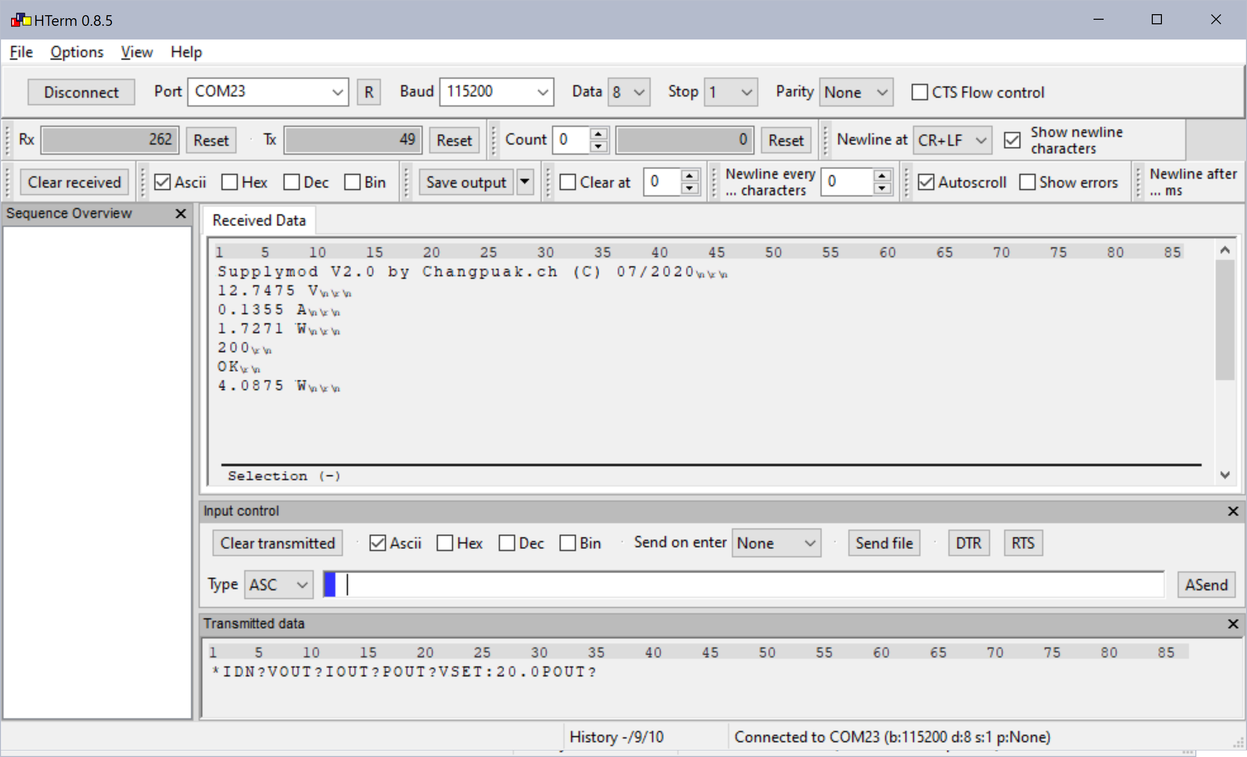
✈ Remote Control of the Powermod
COM SETTINGS :
Set up the COM port inside the PC according to the following list.
• Baud rate: 115200
• Parity bit: None
• Data bit: 8
• Stop bit: 1
• Data flow control: None
COMMAND SYNTAX : VSET:xx.x OR VSET:x.x
Description: Sets the output voltage.
Example VSET:13.8
Sets the voltage to 13.8V
Returns O.K.
IOUT?
Description:Returns the actual output current.
Example IOUT?
Returns the output currents.
*IDN?
Description:Returns the Powermod identification.
Example *IDN?
Returns POWERMOD 2.0 BY CHANGPUAK.CH
SAVE!
Description:Stores the actual Voltage into the Eeprom
Example SAVE!
Returns O.K.
Remote Control with e.g. HTerm 0.8.5 from Tobias Hammer
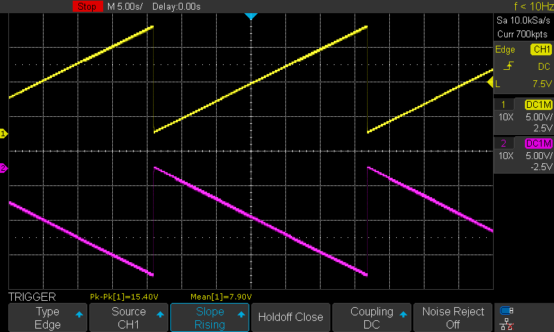
✈ Performance
The standard first test of a new Power Supply : Ramping-up (down). This time in Stereo :-)
✈ What else ?
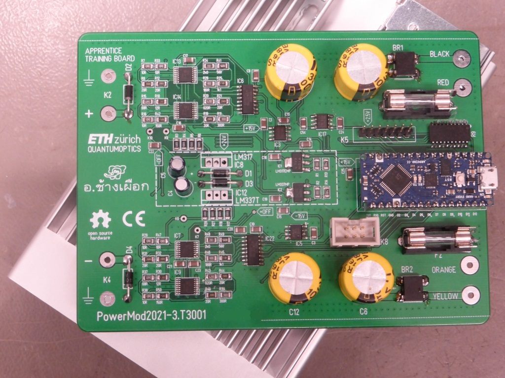
The assembled PCB. The Current Sensor ICs are mounted on the bottom.
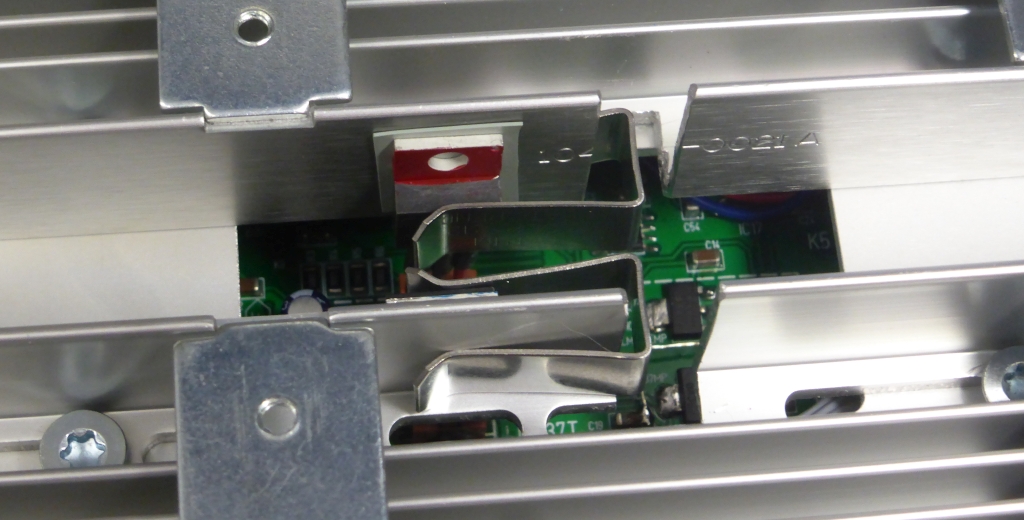
The Voltage Regulators held in place by two clips. No need to colour them - only, if
you plan to disassemble them several times ...
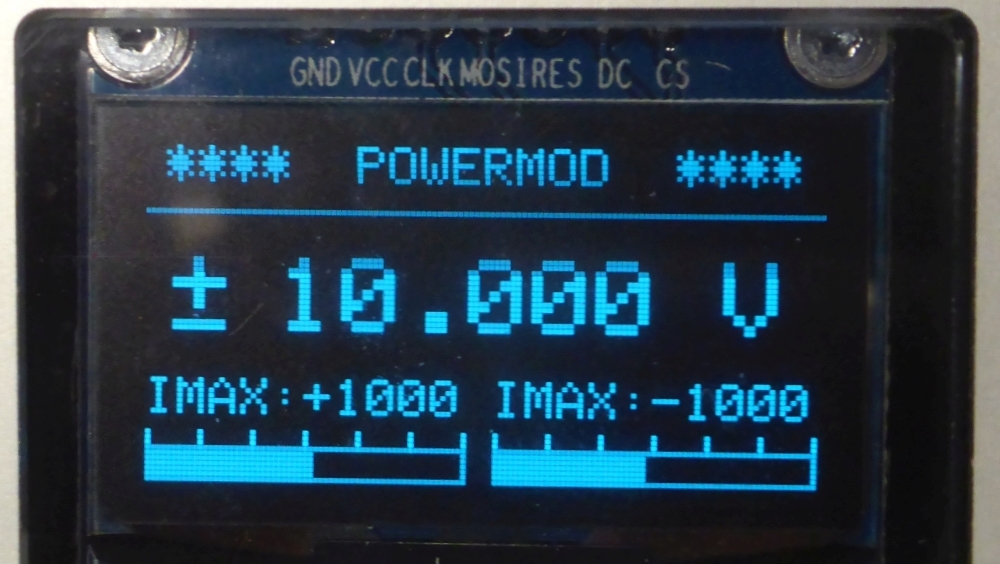
The Current Indicator Bars ... before calibration.
✈ Pitfalls
When screwing the heatsink to the case, double-check, that the screws are not too long.
Otherwise, the pcb cannot be slid into the case.
✈ Share your thoughts
The webmaster does not read these comments regularely. Urgent questions should be send via email.
Ads or links to completely uncorrelated things will be removed.
 ช้างเผือก