 ช้างเผือก
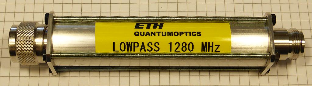
Categories
Statistics
Since 08.08.2014
Counts only, if "DNT = disabled".
216.73.216.233
216.73.216.233
Counts only, if "DNT = disabled".
216.73.216.233
216.73.216.233
Info

เราจะทำแบบวิศวกรผู้ยิ่งใหญ่

28. July 2026
YOUR OPINION •••
average: 9.000, n: 2

When using this form, your ip is stored in order to avoid multiple voting on the same website. That's it.
When using this form, your ip is stored in order to avoid multiple voting on the same website. That's it.
Stepped_Impedance_Lowpass_Coax.php 21028 Bytes 09-11-2014 19:44:50
Stepped Impedance Coaxial Lowpass Filter Designer
An electronics project - for the mechanic in you :-)
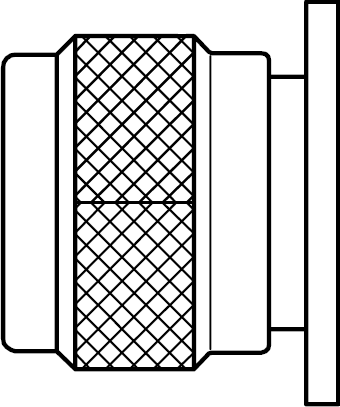
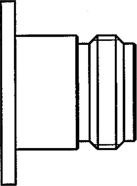
Drawing not to scale. Just for illustration.
Notes :
Soldering the connector is much easier, if you choose an odd number of elements with inductance
at both ends. You may also add pieces of the system impedance (Section #0) as long as required.
For mechanical stability, the minimum wire diameter is limited to 1.0 mm (0.039 inch). This also limits the maximum impedance.
In order to isolate the outer tube from the 'capacitances', we suggest the following materials which have an dielectric constant near 1 (air) : Plastic 1.1, Paper 1.2, ...
In order to isolate the outer tube from the 'capacitances', we suggest the following materials which have an dielectric constant near 1 (air) : Plastic 1.1, Paper 1.2, ...
Assembly and Test
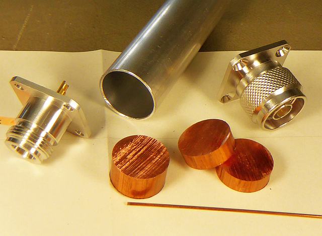
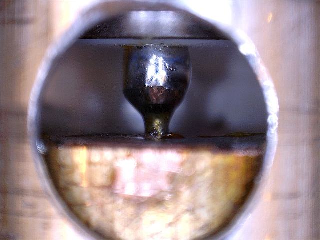
For verification reasons, we designed a Butterworth lowpass, 7th order. Cutoff was 1190 MHz. We have chosen the Low Impedance to be 6 Ω resulting in 18 mm diameter, the High Impedance was 179 Ω resulting in almost 1 mm diameter. Therefore we could use standard copper rods which had to be cut only in length. The outer tube was made approx. 4 mm longer in order to have some space to solder the N-connectors. On one end of the tube, a hole was drilled, so that the inner conductor could be soldered after the assembly. As spacers, we glued 4 carton stripes.
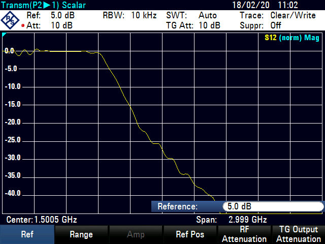
The picture below shows the insertion loss, which was approx. 0.3 dB. It was observed, that the 3 dB corner frequency was at 960 MHz and not - as calculated - at 1190 MHz. As we found no error in the formulas it must be the material. We assume that the 'capacitors' were longer than ordered.
References • Further Reading • Brainfood
Sudipta Das, Dr. S.K.Chowdhury, “Design Simulation and Fabrication of
Stepped Impedance Microstrip line Low Pass Filter for S-band Application
using IE3D and MATLAB“ IJECT Vol. 3, Issue 1, Jan. - March 2012
Note of Thanks
We would like to thank Rob, K7QJ for his valuable feedback in order to make this calculator a 'handy' tool.
✈ Share your thoughts
The webmaster does not read these comments regularely. Urgent questions should be send via email.
Ads or links to completely uncorrelated things will be removed.
|
t1 = 7320 d
t2 = 300 ms |
★ ★ ★ Copyright © 2006 - 2026 by changpuak.ch ★ ★ ★
|

|