 ช้างเผือก
Categories
Statistics
Since 08.08.2014
Counts only, if "DNT = disabled".
216.73.216.203
216.73.216.203
Counts only, if "DNT = disabled".
216.73.216.203
216.73.216.203
Info




เราจะทำแบบวิศวกรผู้ยิ่งใหญ่
15. October 2026
Project Files


YOUR OPINION •••
average: 9.000, n: 1

When using this form, your ip is stored in order to avoid multiple voting on the same website. That's it.
When using this form, your ip is stored in order to avoid multiple voting on the same website. That's it.
PLL_Seminar_2.php 12955 Bytes 04-03-2025 19:13:22
Mini PLL Seminar #2 - Practise
PLL Demoboard • Single Frequency
The PLL Demoboard consists of a Crystal Oscillator with a Divider. You can select Reference Frequencies from 250 Hz to 4 kHz.
As PLL and VCO, a '4046 is used. Together with three programmable Decade Counters a handy Platform is available to study the
nature of a PLL.
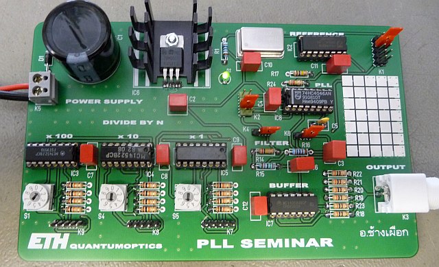
Let's design a PLL !
Requirements :
Output Frequency : 77.5 kHz
Output Frequency : 77.5 kHz
Step 1 - The Divider
As the Demoboard offers Reference Frequencies of 250Hz, 500 Hz, 1kHz, 2 kHz and 4 kHz we obtain the following values for N:
As usual there are more possibilities. We will see later, which value to choose and why.
The 'not possible' values may need a different approach: dual modulus prescaler ...
Reference Frequency | Divider Value (N) | Remarks |
250 Hz | 310 | possible, integer value |
500 Hz | 155 | possible, integer value |
1 kHz | 77.5 | not possible |
2 kHz | 38.75 | not possible |
4 kHz | 19.375 | not possible |
As usual there are more possibilities. We will see later, which value to choose and why.
The 'not possible' values may need a different approach: dual modulus prescaler ...
Step 2 - The VCO (4046)
As the Tolerances are high - and depend on the Supply Voltage, the Temperature and other
Parameters, we dimension the VCO to work at 77.5 kHz +/- 20%.
Using the formulas/graphs in the datasheet or this website, we find:
R1 = 100 kΩ
R2 = 120 kΩ
C1 = 1.5 nF
This results in : Fmin = 60.8 kHz and Fmax = 97.7 kHz whereas 77.5 kHz is somewhere in the middle.
The actual Frequency Range is somehow larger, if the Tuning Voltage goes below 1.1 V or above 3.9 V. Other Solutions are possible as well !!!
Parameters, we dimension the VCO to work at 77.5 kHz +/- 20%.
Using the formulas/graphs in the datasheet or this website, we find:
R1 = 100 kΩ
R2 = 120 kΩ
C1 = 1.5 nF
This results in : Fmin = 60.8 kHz and Fmax = 97.7 kHz whereas 77.5 kHz is somewhere in the middle.
The actual Frequency Range is somehow larger, if the Tuning Voltage goes below 1.1 V or above 3.9 V. Other Solutions are possible as well !!!
Step 3 - The Loop Filter
The Loop Filter is somehow tricky. If we demand a very fast lock-time, the suppression of the Reference-Clock may be insufficient - and
if the Filter is too slow, Oscillation may occur as the Phase shift is to large.
The natural frequency (ωn) is a measure of the response time of the loop whilst the damping factor (ξ) is a measure of the overshoot and ringing.
Ideally, the natural frequency should be high ( 10% * REFCLK ) and the damping factor should be near 0.707 (critical damping).
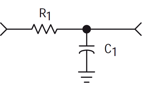
Attempt 1 - Simple R-C-Lowpass
The Schematics |
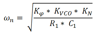
(1) The natural Frequency : ωn |
(2) The Damping Factor : ξ |
 |
 |
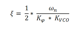 |
Kφ : Phase Detector Gain • KVCO : VCO Gain • KN : Divider Gain, KN = 1 / N
To proceed further, we have to decide which Phase Detector we use, as their Gain is different.
We choose PD2 and therefore get (from the Datasheet) : Kφ = Vcc / 4 * π , Volt/rad
We decide to use REFCLK = 500 Hz and N = 155.
As ωn = 10% of REFCLK yields : ωn = 50 Hz * 2 * π ≈ 314.159 rad/sec.
KN = 1 / 155 ≈ 0.0064561
KVCO = 13.185 kHz / V ≈ 82.84379 * 103 rad/sec/V
Rewriting Formula (1) : (and calculating it)
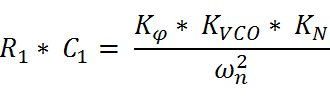
yields in R1 * C1 = 2.1547 * 10-3
We choose C1 = 1 µF and R1 = 2.2 kΩ (other Solutions are also possible !)
Now, let's see what damping factor we have.
Using Formula (2) we calculate ξ = 9.5308 * 10-3.
Ooooops ! This value is far away of the desired 0.707 !
Using this Filter may result in a very long time to get the VCO locked !
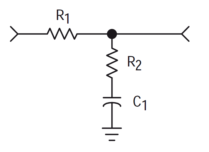
Attempt 2 - Simple R-R-C-Lowpass
The Schematics |
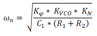
(3) The natural Frequency : ωn |
(4) The Damping Factor : ξ |
 |
 |
 |
Kφ : Phase Detector Gain • KVCO : VCO Gain • KN : Divider Gain, KN = 1 / N
Again, we choose PD2 and therefore get (from the Datasheet) : Kφ = Vcc / 4 * π , Volt/rad
We decide to use REFCLK = 500 Hz and N = 155.
As ωn = 10% of REFCLK yields : ωn = 50 Hz * 2 * π ≈ 314.159 rad/sec.
KN = 1 / 155 ≈ 0.0064561 and ξ = 0.707
KVCO = 13.185 kHz / V ≈ 82.84379 * 103 rad/sec/V
Rewriting Formula (3) :
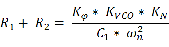
We choose C1 = 10 nF and calulate this expression.
We get : R1 + R2 = 215.4709 * 103 Ω.
Rewriting Formula (4) :

Calculating this expression yields : R2 = -200.7 Ω.
Ooooops ! This is not possible. We decide to increase ξ to ξ = 2.43 as this is still acceptable.
Now, recalculating, we get R2 = 15 kΩ and therefore R1 = 200 kΩ.
LOOPFILTER: C1 = 1 µF, R1 = 200 kΩ, R2 = 15 kΩ, ξ = 2.43, ωn = 314.159 rad/sec
VCO: R1 = 100 kΩ, R2 = 120 kΩ, C1 = 1.5 nF
This is used in the Project : Homebrew DCF-77 Signal Generator
Let's design another PLL !
Requirements :
Output Frequency : 1280 MHz, REFCLK : 10 MHz, N=128
As we use the VCO ROS-1310C+ from MiniCircuits™ we obtain KVCO = 5 MHz / V
(from Datasheet). This equals KVCO = 5 MHz / V * 2 * π = 31.41592 * 106 rad/sec/Volt
and ωn = 10 MHz * 0.1 * 2 * π = 6.2831 * 106 rad/sec.
With N = 128 we obtain KN = 1/128 ≈ 7.8125 * 10-3.
Now, as the VCO delivers 1280 MHz at a Tuning Voltage of around 6 Volt, we have no chance
to reach that in using 5 V Logic. We must insert an Amplifier with Vu = 2 (approx.).
Therefore we get another KAmp = 2.
Output Frequency : 1280 MHz, REFCLK : 10 MHz, N=128
As we use the VCO ROS-1310C+ from MiniCircuits™ we obtain KVCO = 5 MHz / V
(from Datasheet). This equals KVCO = 5 MHz / V * 2 * π = 31.41592 * 106 rad/sec/Volt
and ωn = 10 MHz * 0.1 * 2 * π = 6.2831 * 106 rad/sec.
With N = 128 we obtain KN = 1/128 ≈ 7.8125 * 10-3.
Now, as the VCO delivers 1280 MHz at a Tuning Voltage of around 6 Volt, we have no chance
to reach that in using 5 V Logic. We must insert an Amplifier with Vu = 2 (approx.).
Therefore we get another KAmp = 2.
to be continued ...
✈ Share your thoughts
The webmaster does not read these comments regularely. Urgent questions should be send via email.
Ads or links to completely uncorrelated things will be removed.
|
t1 = 7399 d
t2 = 229 ms |
★ ★ ★ Copyright © 2006 - 2026 by changpuak.ch ★ ★ ★
|
|


