 ช้างเผือก
Categories
Statistics
Since 08.08.2014
Counts only, if "DNT = disabled".
216.73.216.233
216.73.216.233
Counts only, if "DNT = disabled".
216.73.216.233
216.73.216.233
Info

เราจะทำแบบวิศวกรผู้ยิ่งใหญ่

28. July 2026
YOUR OPINION •••
average: 8.500, n: 2

When using this form, your ip is stored in order to avoid multiple voting on the same website. That's it.
When using this form, your ip is stored in order to avoid multiple voting on the same website. That's it.
Arduino-Tobimod.php 14709 Bytes 04-03-2025 19:11:04
Arduino RF Scalar Network Analyzer Tobimod
A 400 MHz, 80 dB Setup with the AD9912, AD8307 e.a.
This is a combination of several successful components. We used :
The Arduino Shield 'Tobi'
DIY Dual Directional Coupler, 5 - 1000 MHz, 20 dB
Logarithmic Amplifier with the AD8307
And the result is a yet another niftyham radio gadget Quantumoptics Lab Tool.
The Arduino Shield 'Tobi'
DIY Dual Directional Coupler, 5 - 1000 MHz, 20 dB
Logarithmic Amplifier with the AD8307
And the result is a yet another nifty
✈ The building Blocks • Functional Description
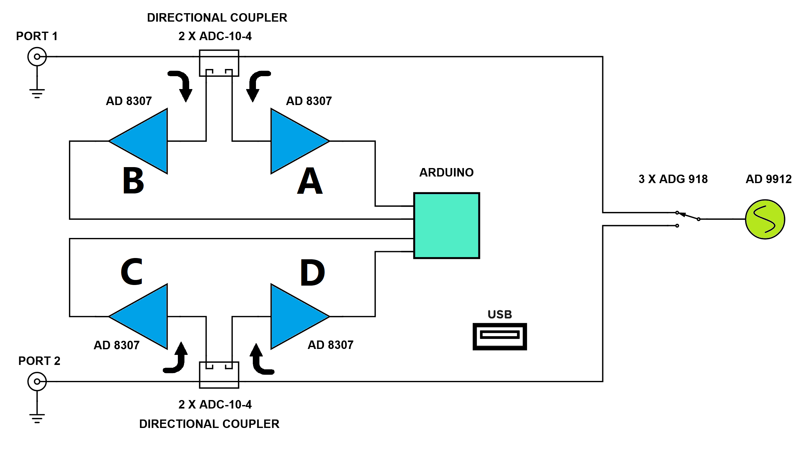
This is a full 2 Port Scalar Network Analyzer. The mastermind of this design is a Python Script which handles the data.
The Tobimod itself holds the Main Frequency Source (AD9912, 1 GSPS Direct Digital Synthesizer with 14-Bit DAC). It is switched via 3 X ADG 918 (Wideband 4 GHz, 43 dB Isolation at 1 GHz, CMOS 1.65 V to 2.75 V, 2:1 Mux/SPDT) to either Port 1 or Port 2. The switch terminates the other path with 50 Ω. We use three of them to reduce crosstalk. In the path are two dual directional couplers (each 2 X ADC-10-4, from MCL).
The outputs from the dual directional couplers are directly converted to a dc voltage by an AD 8307 (Low Cost, DC to 500 MHz, 92 dB Logarithmic Amplifier).
A REF03 (Precision 2.5 V Voltage Reference) supplies the Arduino Nano Every with a precise voltage reference and limits the range to 2.5 V - the maximum output of the AD8307.
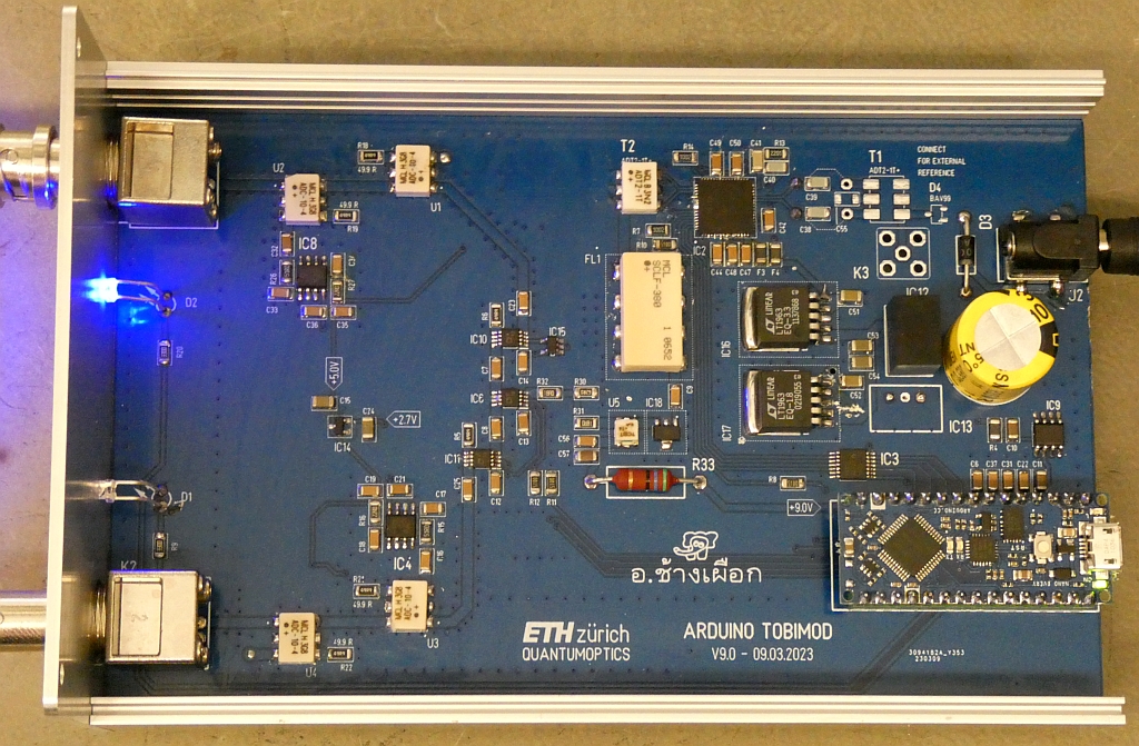
Not much inside, but those few parts really do an awesome job !
DO NOT FORGET TO ADD RF ABSORBING FOAM.
✈ The RF Source : AD 9912, running at 1 GHz
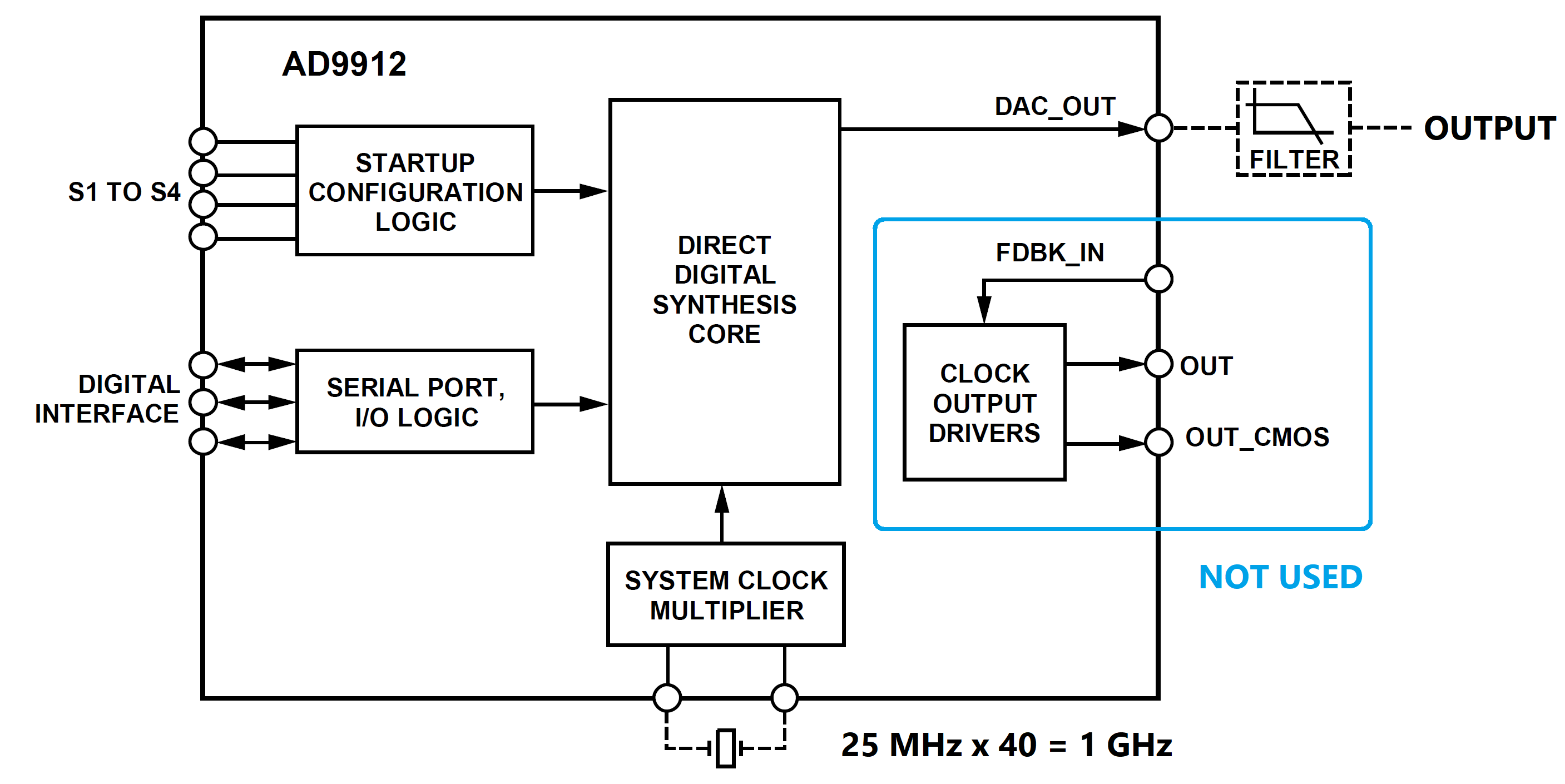
AD9912 Block Diagram. Drawing courtesy of Analog Devices.
The workhorse of this design is the AD9912 (1 GSPS Direct DigitalSynthesizer with 14-Bit DAC). Even so there are designs out there, using this DDS at 1.3 GHz clock, we decided not to overclock the chip that much. We use the recommended transformer (ADT2-1T+, from MCL). The output is lowpass filtered by an SCLF-380+ (MCL) and the amplified by a GALI-6+ (+12 dB, max. +18 dBm, by MCL). After the amplification, an attenuator lowers the level. This amplification - attenuation scheme actually creates a lot of isolation.
The 48-Bit hurdle was addressed in using the unsigned long construction. This allows 32-Bit calculations on a system like the Arduino Nano Every. Anyway, the two lowest significant bytes are always set to 0x23 and 0x41 (phone number of the webmaster :-) This causes an offset of Freq < 999 Hz. And yes : the measurement below was made, before the programming of the chip was complete. The crystal oscillator was not calibrated.


✈ The ADC ... is the Arduino. Fed by 4 x AD 8307.
The analog to digital conversion is done by the Arduino Nano Every. With the available 10 Bits
and the external reference set to 2.5 V we can cover the entire range of the AD8307.
A resolution better than 0.1 dB is to be expected.
The Conversion from Volts to dBm is done inside the Arduino. We use a straight line to interpolate. The formula looks like this :

The Slope and Intercept is frequency dependant. We use the values measured at 101 MHz. As we use only differences in power levels, the result is not that far from the truth.
From the project Arduino Levelmod we copied the values for Slope := 39.847 dB/V and Intercept := - 85.541 dBm.
With some easy math, we can then calculate the power ratios. Using the logarithmic value, it is as simple as a subtraction. The table below shows which values to use ...
The Conversion from Volts to dBm is done inside the Arduino. We use a straight line to interpolate. The formula looks like this :
The Slope and Intercept is frequency dependant. We use the values measured at 101 MHz. As we use only differences in power levels, the result is not that far from the truth.
From the project Arduino Levelmod we copied the values for Slope := 39.847 dB/V and Intercept := - 85.541 dBm.
With some easy math, we can then calculate the power ratios. Using the logarithmic value, it is as simple as a subtraction. The table below shows which values to use ...
| PARAMETER | RF Source @ PORT | FORMULA |
| S11 | 1 | A - B |
| S21 | 1 | C - A |
| S12 | 2 | D - B |
| S22 | 2 | D - C |
✈ Remote Control of the Tobimod
COM SETTINGS :
Set up the COM port inside the PC according to the following list.
• Baud rate: 115200
• Parity bit: None
• Data bit: 8
• Stop bit: 1
• Data flow control: None
Set up the COM port inside the PC according to the following list.
• Baud rate: 115200
• Parity bit: None
• Data bit: 8
• Stop bit: 1
• Data flow control: None
COMMAND SYNTAX :
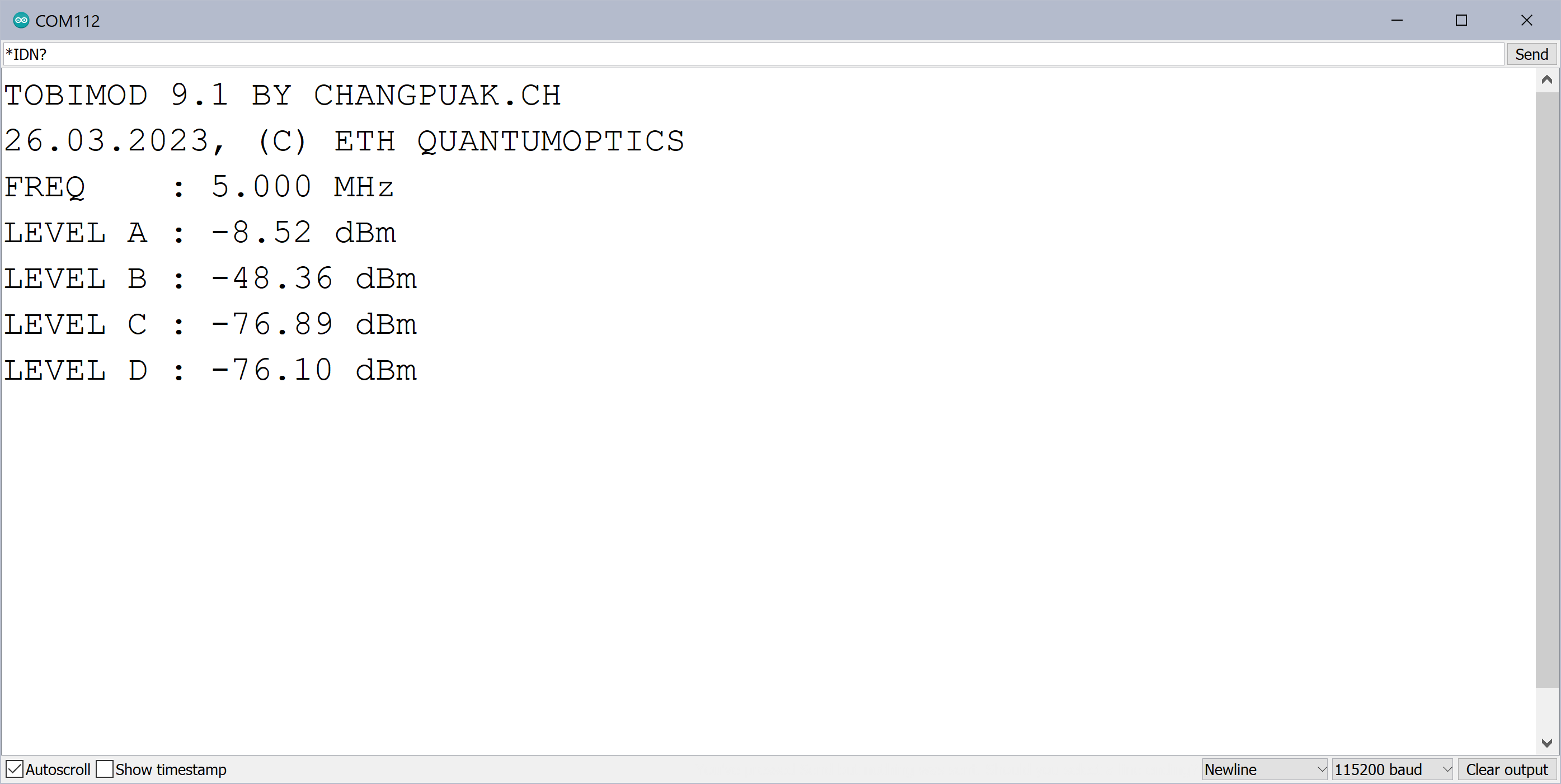
*IDN?
Description: Returns the Device's identification.
Example *IDN?
Returns Tobimod 9.0 BY CHANGPUAK.CH
Returns 26.03.2023, ETH QUANTUMOPTICS
Returns FREQ : 100.000 MHz
Returns LEVEL A : -8.0 dBm
Returns LEVEL B : -48.0 dBm
Returns LEVEL C : -70.0 dBm
Returns LEVEL D : -70.0 dBm
SETF:xxxxx
Description: Sets the RF Frequency of the Source. Unit is MHz.
Example SETF:10.000
Returns NIL (nothing)
SETC:x
Description: Sets the Channel / Source
Example SETC:1
Returns NIL (nothing), but LED indicator mayst change
GETA?
Description: Measures the Amplitude. Unit is dBm. Port 1 forward Power.
Example GETA?
Returns -19.9
GETB?
Description: Measures the Amplitude. Unit is dBm. Port 1 reflected Power.
Example GETB?
Returns -19.9
GETC?
Description: Measures the Amplitude. Unit is dBm. Port 2 reflected Power.
Example GETC?
Returns -19.9
GETD?
Description: Measures the Amplitude. Unit is dBm. Port 2 forward Power.
Example GETD?
Returns -19.9
✈ Downloads


✈ Tests • Self Tests after Assembly
A 50 Ω Termination at Port 1 lets the B-value drop to -48 dBm
(coupler loss not taken into account)
(coupler loss not taken into account)
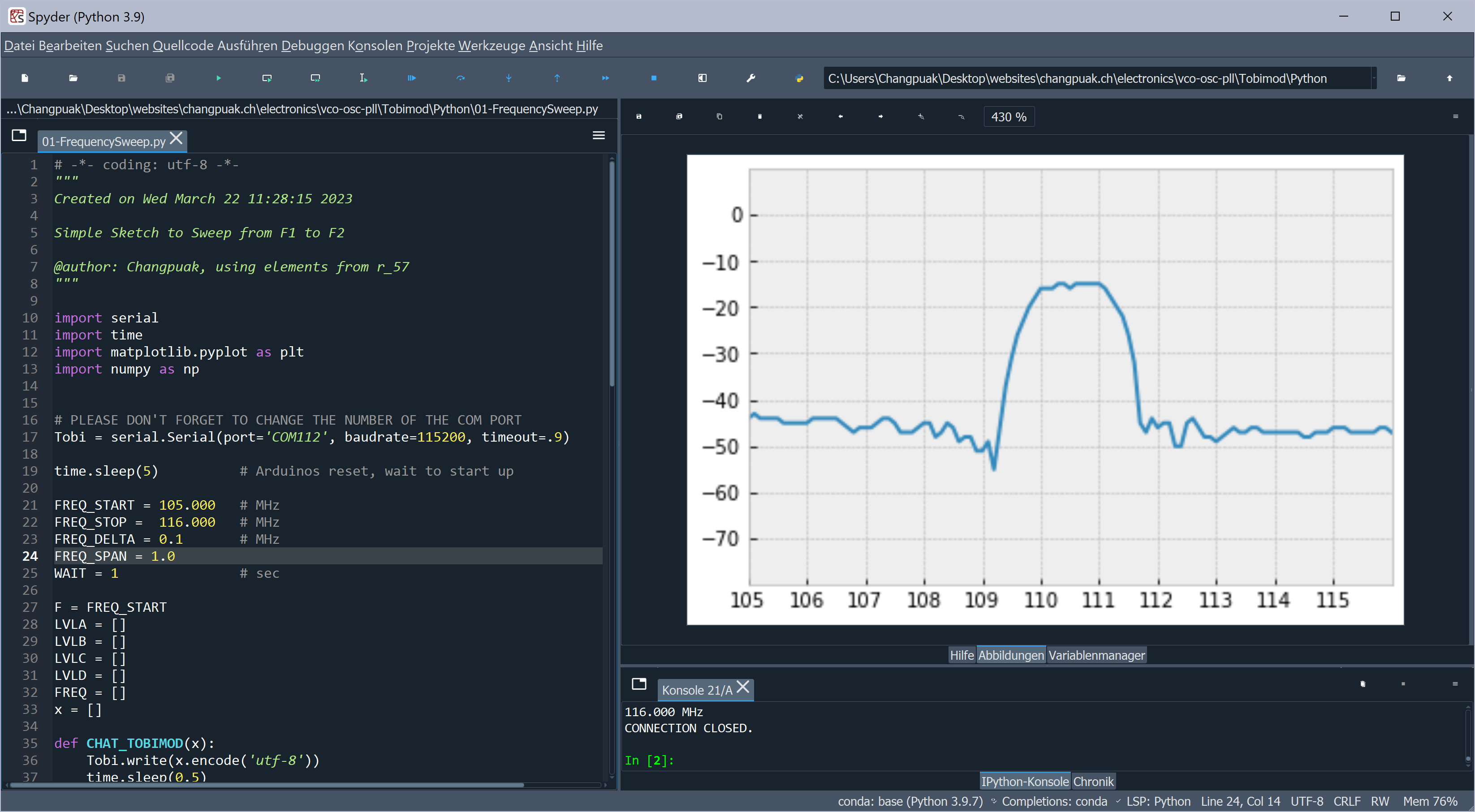
A Bandpass from MiniCircuits (ZFBP-70+), as seen with the Python Script
(not calibrated)
(not calibrated)
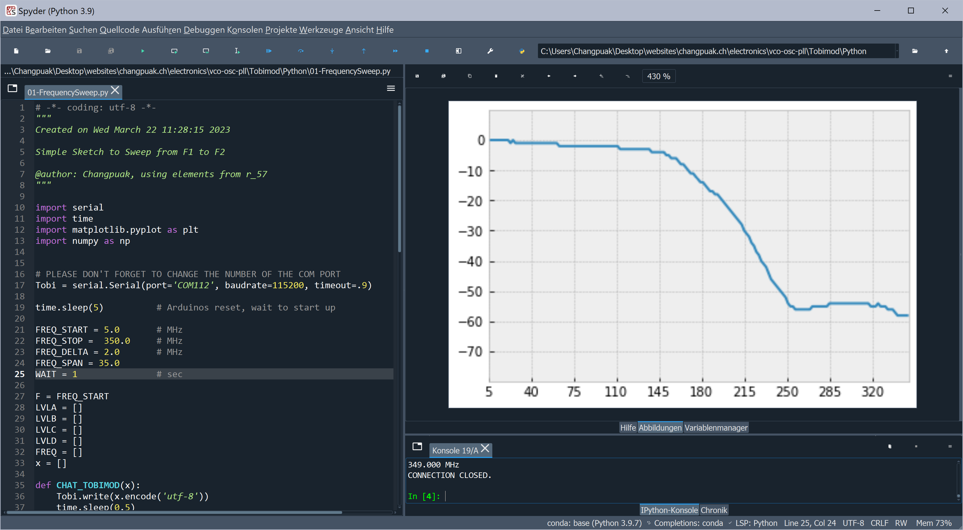
A Lowpass from MiniCircuits (SLP-150), as seen with the Python Script
(not calibrated)
(not calibrated)
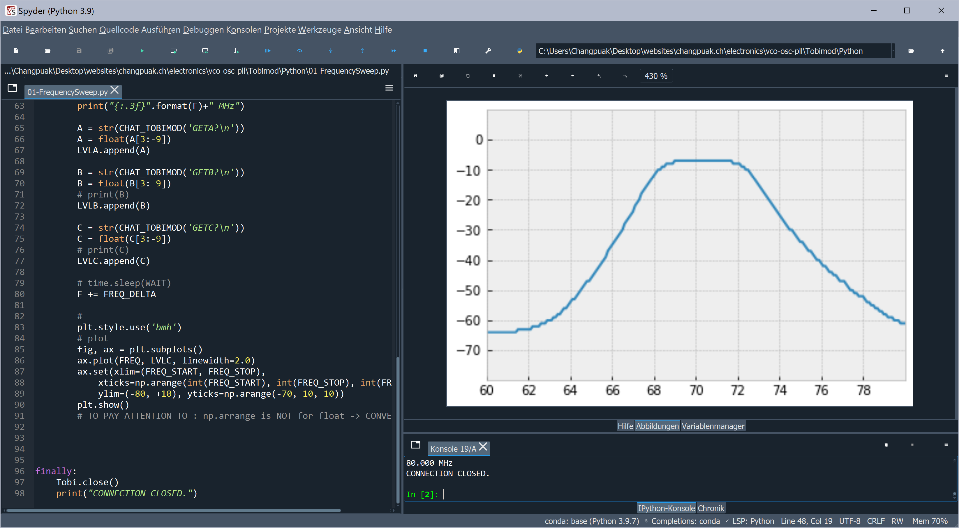
A DECT IF Bandpass, centered around 110.592 MHz, as seen with the Python Script
(not calibrated)
(not calibrated)
✈ Scalar Network Analyzer vs. Vector Network Analyzer
A vector network analyzer measures the gain and phase value, a scalar network analyzer
measures only the gain. To measure only a scalar is not limiting the expert, as they
use their fingertip to add some Picofarad. If the signal gets worse, your design is
already in the capacitive area.
✈ Share your thoughts
The webmaster does not read these comments regularely. Urgent questions should be send via email.
Ads or links to completely uncorrelated things will be removed.
|
t1 = 7320 d
t2 = 260 ms |
★ ★ ★ Copyright © 2006 - 2026 by changpuak.ch ★ ★ ★
|

|