A 2.7 GHz Spectrum Analyser based on the RF-Explorer 3G+ Shield
This is a Spectrum Analyser based on the RF-Explorer 3G+ Shield from
Seeedstudio.
The Software was written by Mr. Mirco Dill. This was his final thesis aka "IPA" which is the Individual Personal
Work an apprentice does at the end of his education. Some small adjustements were
suggested by me. The device is very welcome by our students/labs.
UNIT
RANGES • REMARKS
Frequency
15 - 2700 MHz
Input
Normal, LNA, 30dB Attenuator
Amplitude Resolution
0.5 dB
Dynamic Range
-130 dBm to +10 dBm
Resolution Bandwidth
automatic 3 kHz to 600 kHz
Maximum Input Power
+ 30 dBm (Damage Level)
Average Noise Floor Level
-120 dBm (LNA enabled)
Frequency Stability and accuracy
10 ppm (typ)
Amplitude Stability and accuracy
+/-3 dB (typ)
Frequency Resolution
1 kHz
The specifications are mainly those of the shield "RF-Explorer 3G+" from
Seeedstudio
or, to be more precise from the shield designed by Mr. Ariel Rocholl.
✈ Motivation
In our labs, a lot of exclusive testgear (e.g. spectrum analysers) is just used to see if a carrier is there or not.
Those devices very likely may endure that emotionally, but freeing them for a more sophisticated task was the self given challenge.
We therefore created a project, based on the Arduino/Genuino Due, a shield "SPECTRE" as well as the
RF Explorer 3G+ IoT Shield for Arduino.
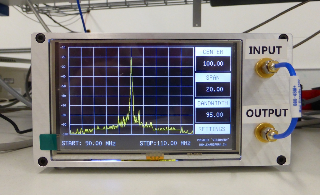
Together with a 5.0" 40-pin TFT Display - 800x480 with Touchscreen (from Adafruit) this should make a nice DIY Spectrum Analyser.
✈ Hardware
The project consists of an Arduino/Genuino Due, a shield "SPECTRE" as well as the
RF Explorer 3G+ IoT Shield for Arduino.
The display is a 5.0" 40-pin TFT Display - 800 x 480 px with Touchscreen (from Adafruit, PID: 1596)
with a driver (RA8875 Driver Board for 40-pin TFT Touch Displays PID: 1590).
The Shield "SPECTRE" also offers the possibility to add an eeprom (as the due has no such thing).
It also has a connector for a rotary encoder as well as a small oled (128 x 64px).
Two bnc outputs are connected to DAC0 and DAC1. It shall be used to output the rssi level, when in zero span mode.
This can be used to lock something on the amplitude of a carrier. (This may be useful, if you beam atoms from one
vacuum chamber to another :-)
A buffer, NC7SZ125M5X, connected to TX2 allows this shield to be used as a PRBS generator. Shieldname
yet unknown, but our youngest phd is working on that.
Of course are we curious :-)The stacked shields with the reference (right)
First iteration showing GSMThe tft driver, courtesy of Adafruit
✈ Downloads
✈ Share your thoughts
The webmaster does not read these comments regularely. Urgent questions should be send via email.
Ads or links to completely uncorrelated things will be removed.
 ช้างเผือก