When using this form, your ip is stored in order to avoid multiple voting on the same website. That's it.
SupplyMod-R.php 10515 Bytes 11-09-2025 12:26:46
Supplymod-R ... R like Recycling
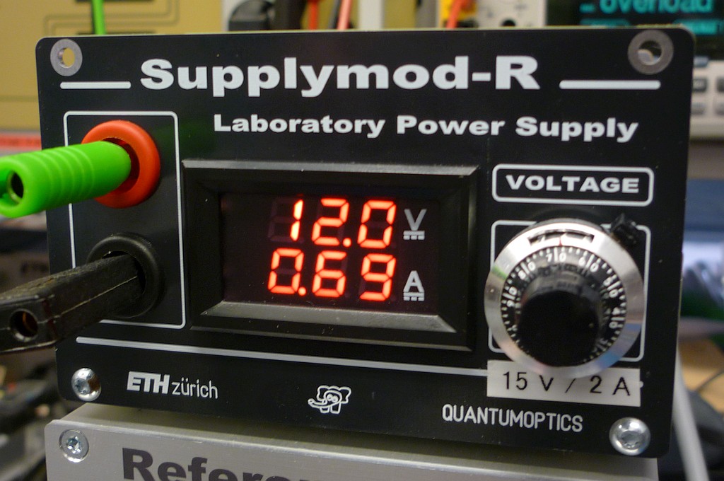
A Voltage Supply, 15 V or 30 V, 2.5 A, with the LT1074
The Prototype ... very budget friendly
✈ Motivation
As our honourable boss is approaching the status of "emeritus", a lot of "too nice to throw" toroidal
transformers are happy to get a second chance to perform - in this Power Supply. As it uses only jellybean
components (like the LT1074) this is a very universal Buck Converter with Output Voltage Range of 2.5V
to 50V. Maximum voltage depends on your transformer, and the available space (hole in the pcb) allows
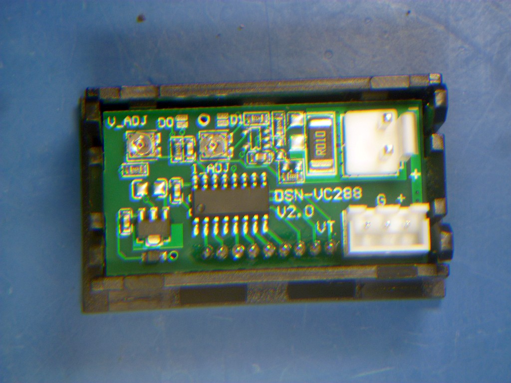
for diameters up to 90 mm. A budget friendly 100V/10A LED Digital Voltmeter/Amperemeter from Ali
handles that displaying stuff. All it needs is a supply of ≈ 12V/15mA.
✈ The Design
The design is straightforward and follows the recommendations in the datasheet. As 50 µH inductors
are hard to find, we used a 47 µH (PCV-0-473-05L, 6A, 10%, 35 mΩ from Coilcraft) instead.
It was chosen by formfactor, as the pcb was already in production. The bridge rectifier (MSB30M-13)
is mounted on the bottom side, in order to save space. For the capacitors, we used the same type (REF1020471M050B from Kyocera AVX)
in order to reduce BOM. The diode used is an SB560 (Schottky Diode, 5 A, 60 V, 650 mV), as it was in our
treasure chest.
A view inside ... not much there ... the LT1074 does it all
The DVM from Ali displays Volts and Ampere ...... and 1.2 € per piece is unbeateable !!!
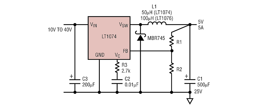
✈ The Working Horse : LT1074 (40V), LT1074HV (60V) from LT
Application Circuit - Drawing courtesy of Linear Technology, now Analog Devices
The LT1074 is the Buck (= step-down converter, used here) / Boost Converter. Besides the classical ingredients, several design innovations
make this an anwesome component. The datasheet says :
"The LT1074 uses a true analog multiplier in the feedback
loop. This makes the device respond nearly instantaneously to input voltage fluctuations and makes loop gain
independent of input voltage. As a result, dynamic behavior of the regulator is significantly improved over previous
designs."
✈ Inductor Selection
Often overlooked by young engineers is the fact, that inductors have a maximum current capability,
and when going beyond those values, saturation is likely to occur. Luckily, the manufacturer suggests
a value of 50 µH to be used. This value mainly is defined by the switching frequency, which is 100 kHz.
But there are many versions avilable, out there.
The first figure to have a look at is the DC resistance. It is directly related to the inductor’s
conduction loss. As it will produce heat (= wasted energy), smaller values are to be preferred.
Second thing to look at is the shielding. There are shielded and unshielded versions available.
It is recommended to use a package with magnetic shielding, as it generates less noise and better
EMC performance. And the third thing to look at is the maximum current. The peak current is approx.
120 % of the maximum output current. As we specified 2.5 A, our inductor must be able to handle at least
1.2 x 2.5 = 3 A. The inductor used causes a temperature rise of 40 °C at 6 A. A lot of headroom.
• DC resistance : choose smallest possible value
• Shielding : choose a shielded inductor for better EMC performance
• Current : choose a value having > 150 % of the max. output current
✈ Downloads
✈ Special Components used here
ITEM
SUPPLIER
U/I meter
DC0-100V 10A LED Digital Voltmeter Amperemeter from Ali
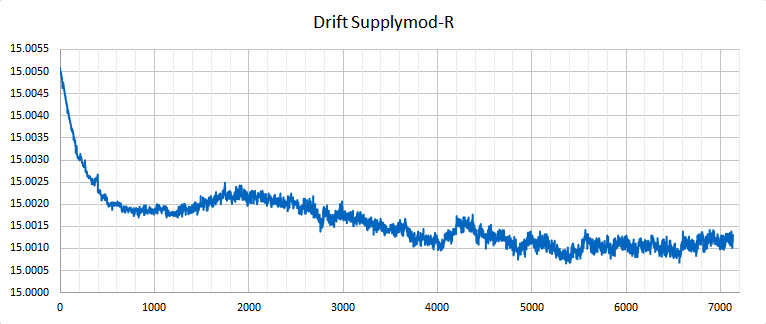
The voltage drift is mainly introduced by the internal voltage reference of the LT1074 plus the potentiometer and
the resistor in the feedback loop. The datasheet forgot to mention any drift characteristics. For this measurement,
the Supply was set to output 15 V, Current drawn was 850 mA. Within the first four hours
after power-up, we see that it reaches a stable state after approx. 2 hrs.
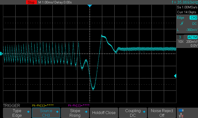
Response to Load Changes. Step from 1760 mA to 160 mA, Voltage set to 15 V
The Power Supply needs about 2 ms to regulate for jumps in load changes. The ripple on the left (≈ 400 mVpp)
is under heavy load conditions.
✈ Share your thoughts
The webmaster does not read these comments regularely. Urgent questions should be send via email.
Ads or links to completely uncorrelated things will be removed.
 ช้างเผือก