To be honest ... we brewed this in the office, after work ;-)
And yes, this is my personal masterpiece
The receiver uses a downconverter concept (supersonic heterodyne). The intermediate frequency is 36.0 MHz. Some focus was put on the use of standard parts,
which should make the replication easier. Operation on 13.8 V battery is possible. The AM demodulation is done with a low-cost AD8361
(True Power Detector). This is NOT a youngplayer's project. From the first dream to the first noise (out of the loudspeaker)
it took almost 3 decades :-(
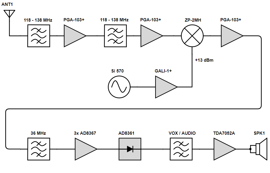
✈ Block diagram • the functional blocks • concept
Starting at the rf input, the signal passes an airband bandpass, followed by a low noise amplifier and two 10 dB attenuators. This section is
used twice, in order to have a low insertion loss of the Direct Coupled Resonator Bandpass Filter before the LNA whilst having a good selectivity.
The first mixer is a ZP-2MH (from MCL), demanding + 13 dBm LO power, which is delivered by a Si570.
After the first mixer, there is again an amplifier in order to have a broadband termination for the mixer.
Following is a Crystal Bandpass Filter at 36.0 MHz.
The if-amplifier is build with three AD8367. It offers a dynamic range of 120 dB.
Finally, the demodulation is done with a power sensor from Analog Devices (AD8361).
Following is a audio power amplifier (TDA7052A) which also includes the squelch circuit.
An Arduino/Genuino Micro handles the (one wire) keyboard, the lcd as well as the programming of the oscillator.
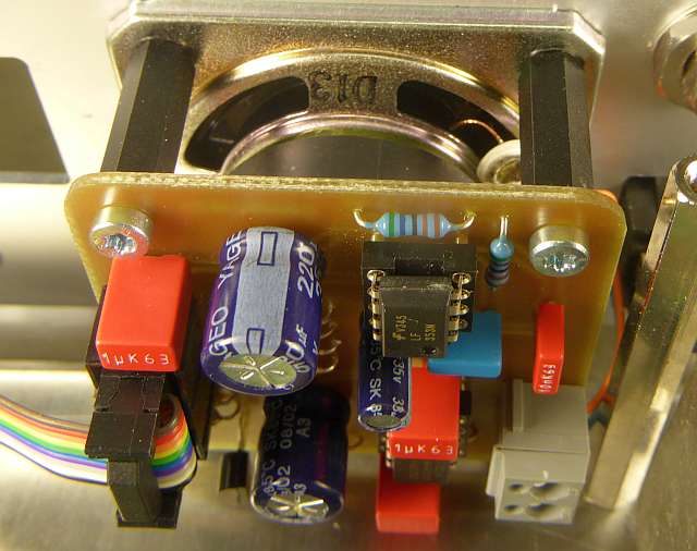
✈ AIRBAND BANDPASS FILTER WITH LNA AND ATTENUATORS
After having calculated/simulated some qualified candidates (all with 3x AIAC1812, 68 nH), we finally arrived at the
Direct Coupled Resonator Bandpass.
It offers the most attenuation at the image frequencies and the trimmer capacitors (GSX366) promised some freedom when it comes to adjusting
the passband to the desired location. The bandpass has been duplicated in order to lower the insertion loss before the first amplifier (PGA-103+).
After the two amplifiers, there are two 10 dB attenuators (MAATSS0018) which can be switched, depending on the position of the 'rf-gain' potentiometer.
By that, we can select between 10 dB, 20 dB, 30 dB, 40 dB or 50 dB of gain. The filter was assembled on a double sided pcb, bottom layer was ground.
Power consumption is 5 V, ≈ 190 mA.
GAIN
NF
Att. A
Att. B
Att. C
Att. D
50 dB
0.50
0 dB
0 dB
0 dB
0 dB
40 dB
0.50
0 dB
0 dB
10 dB
0 dB
30 dB
0.51
0 dB
0 dB
10 dB
10 dB
20 dB
0.66
10 dB
0 dB
10 dB
10 dB
10 dB
1.97
10 dB
10 dB
10 dB
10 dB
Calculated values for Gain and Noise Figure for various settings.
We used the Cascaded Noise Figure Calculator for that. For the measurements
below, a 50 dB attenuator has been used. Power from the tracking generator was 0 dBm. At the time, the attenuators were tested, the bandpass was not yet
fully adjusted.
All attenuators engaged. Gain ≈ 10 dBAll attenuators off. Gain ≈ 50 dB
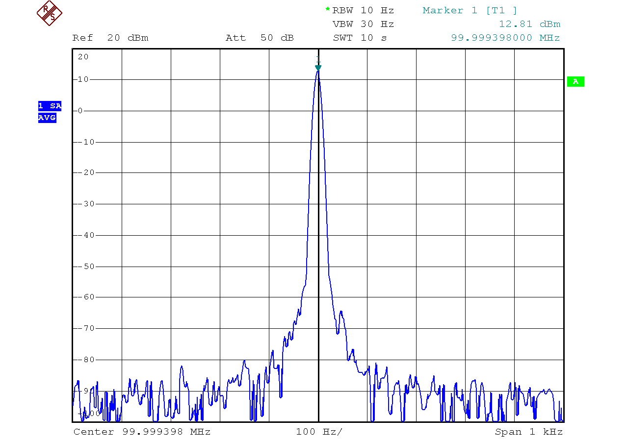
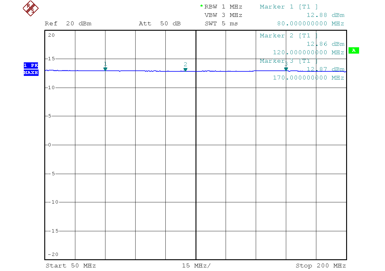
✈ The Local Oscillator : Si-570
This board is a derivative of the Micromod RF Synthesizer. Two attenuators
and an amplifier are used to adjust the output power to +13dBm. The heatsink gets warm, as it has to dissipate almost 1.4 W. Use the biggest possible heatsink or reduce
the input voltage. You will find more information about this calibration stuff on the above mentioned Micromod Synthesizer Website.
+13 dBm of LO-powersuspiciously flat amplitude response
✈ The Mixer : ZP-2MH from MiniCircuits
As it mayst have been guessed from the LO section, the mixer is a 13 dBm type. We use the model ZP-2MH from MiniCircuits.
The only luxury here is that this one comes in a case with sma connectors. No need to do re-invent the wheel ...
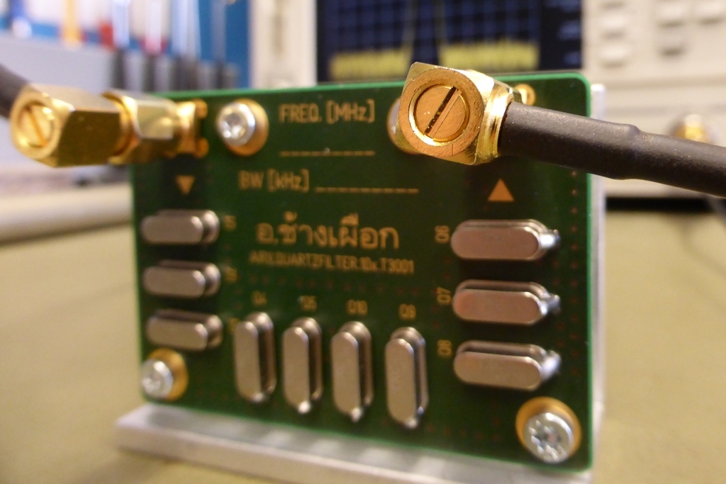
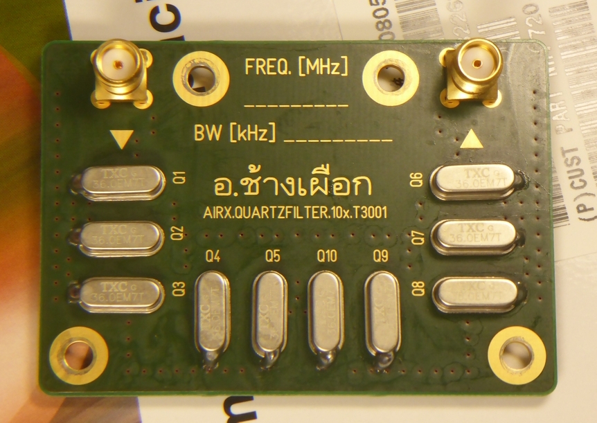
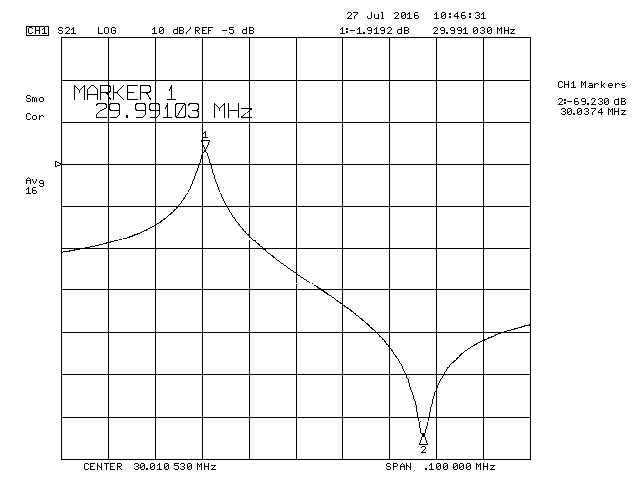
✈ IF CRYSTAL FILTER @ 36.0 MHz, IL : 9 dB, BW : 5.5 kHz
As this receiver is intended for airband, the bandwidth of the if-filter is given by the channel-spacing of 8.333 kHz, therefore a suiteable filter-bandwidth
would be approx. 6 - 8 kHz. As we wanted to realise this filter using crystals, a crystal in the range of 5 ... 20 MHz seemed appropriate. 36 MHz has
been (finally) chosen because this frequency is widely available and such a high intermediate frequency allows the LO to be ouside the RF passband.
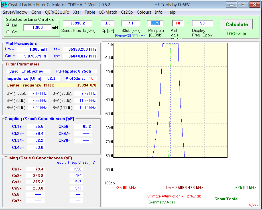
The design of the crystal filter follows the procedure as mentioned elsewhere on this website.
And yes, as it is good use in aviation, we cross-checked that with "Dishal2052.exe".
For our 36 MHz crystals (36 MHz, ±50ppm Crystal, 20pF, 80 Ohm, -20°C to 70°C, HC49/US, DIGI-KEY), we measured an fs = fs=35.9902 MHz, fp = 36.04402 MHz
and a capacitance of 3.3 pF. (Yes, one single piece).
Calculation yields : Cs = 9.877fF fF and Ls = 1.980 mH. The matching (S11) was in the range
of 13 - 16 dB (in the passband).
Top LayerDishal V2.0.5.2 predicts this
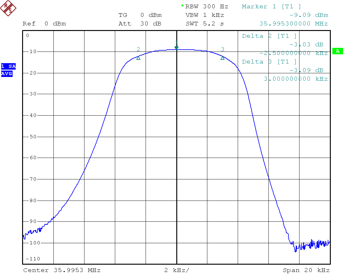
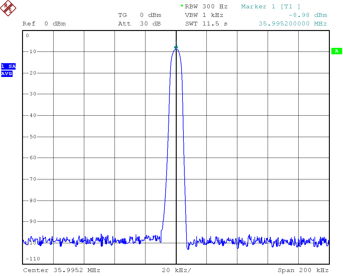
S21 (Narrowband)S21 (Wideband)
✈ Additional Notes on Crystal Filters
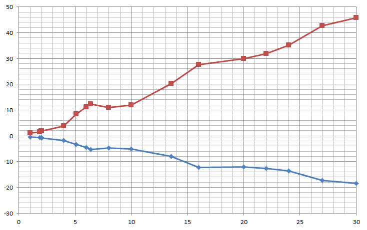
Fs and Fp in [kHz] vs. Frequency [MHz]A 30 MHz HC49/US crystal in the test fixture
Note to the left graph : The difference of the series resonance frequency and the
parallel resonance frequency may be used for a sophisticated guess regarding the
maximum possible bandwith of the filter. The graph shows the measurement of a lot of crystals out of my treasure-box. Choose such a frequency,
where fp-fs is at least twice the desired bandwidth of the filter. This allows the use of larger capacitors which reduces the
influence of stray capacitances.
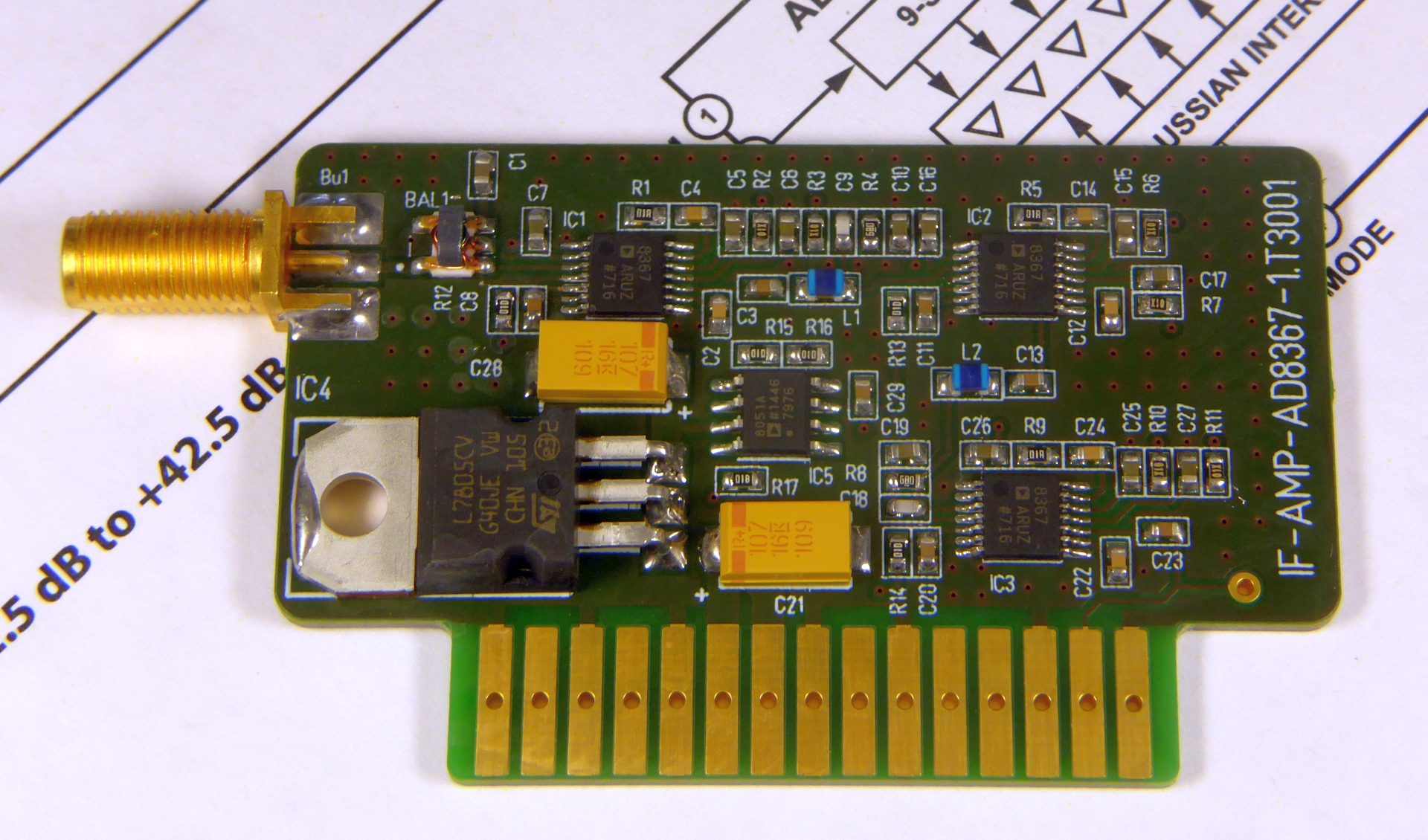
✈ IF Amplifier (3x AD8367)
The if amplifier was inspired by the impressive specifications in the datasheet of the AD8367.
As the noise floor is at -135 dBm (bandwidth: 8.33 kHz) and the rf-preamplifier has a gain of about 50dB, we need an additional 85dB of gain
(worst case) to arrive at 0dBm for the demodulator. With three amplifiers, an AGC gain range of
approx. 120 dB is available. Every stage is controlled by it's own on-chip, square-law detector and the circuit used is that of the
AGC mode of operation, which requires that the correct gain direction is chosen. Specifically, the gain must fall as VAGC
increases to restore the needed balance against the setpoint. Therefore, the MODE pin must be pulled low. For the display,
the three detector output voltages are summed up.
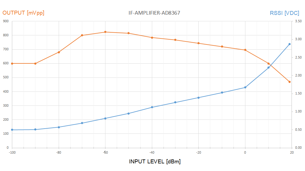
The characteristic of the if amplifier with an unmodulated carrier @ 36 MHz
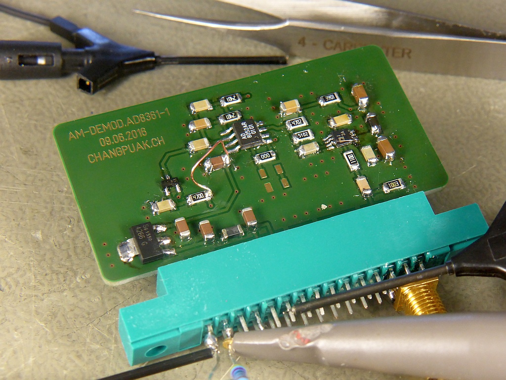
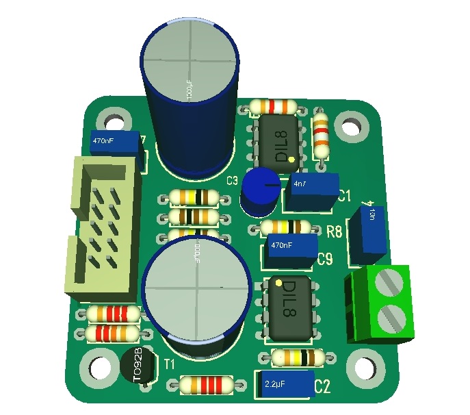
✈ AM Demodulator • AD8361
The AD8361 is a mean-responding power detector. It is intended for true power measurement of simple and complex waveforms.
Says the datasheet. We hope that it will not get emotionally damaged, when used here as an AM-demodulator. It is operated
in Supply Referenced Mode, as it turned out, that the Ground Reference Mode introduced distortion, when the modulation
depth is larger than 50%. And according to some BigG Research, A3E uses a modulation depth of 85%.
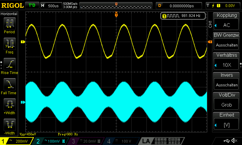
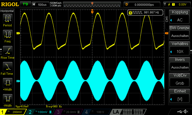
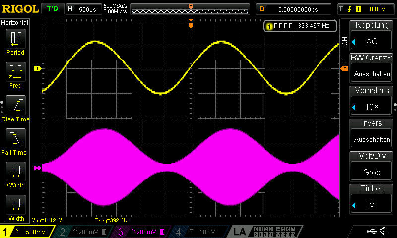
For the graphs below, we used a 10.7 MHz carrier with -10 dBm. Modulation depth and audio frequency vary.
The recovered audio signal (now) looks nice, i.e. THD < 1% (no distortion visible). This board uses approx. 10 mA at 13.8 V supply.
Input level should be -10 dBm ... 0 dBm. As the 6-Lead SOT-23 Package offers Ground Reference Mode Only, we suggest you use the
8-lead MSOP type.
✈ AUDIO AMPLIFIER • TDA7052A
What the Layout program suggests ...... and how it finally looked like
The TDA7052A was chosen, because it offers the possibility to mute the output - just pull the VC pin low.
This feature makes the design of the squelch circuit very comfortable. The option of setting the volume
with a resistor at the VC pin was not used, instead a voltage divider (110kΩ • 10kΩ) generates a stable 1.0 V from the
stabilised 12 V supply. The gain therefore becomes Vu = 10 or G = +20 dB. A large capacitor at this pin is necessary
to suppress heavy oscillations followed by a suicide of the chip. In case the amplifier draws more current (due to large amplitudes)
the supply (and the voltage at VC pin) will be reduced due to R11 (22Ω).
✈ POWER SUPPLY • LM2940/7812 & 7805
The Power Supply is kept very easy. In order not to generate noise, only linear regulators have been used. A heatsink guides the heat away. The only
protection circuit is a Schottkydiode to avoid damage from wrong polarity and a zenerdiode (24 V) to protect the circuit from overvoltage.
Where low noise supply is necessary, the boards have their own regulators. (e.g. IF-Amplifier, AM-Demodulator,...)
The on/off switching is done by a IPP45P03P4L-11 (OptiMOS®-P2 Power-Transistor), inspired by
Bill Herd's "LEARN AND BUILD A HIGH SIDE SWITCH" on HACKADAY.
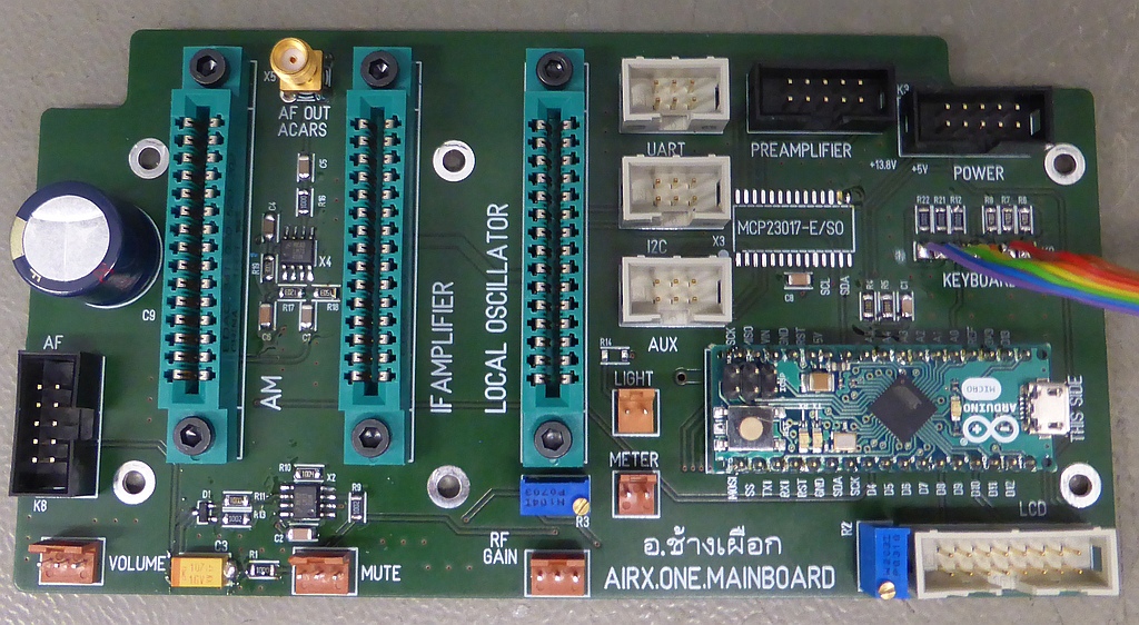
✈ The Microprocessor Board • Arduino/Genuino Micro
This board is designed straightforward. On the left side, it holds the squelch
circuit. Its main task is to scan the keyboard, update the LCD as well as program the local oscillator (Si570).
✈ The Keyboard (One Wire Keypad)
We first tried to get away with the "standard One Wire Keypad" solution which is found quite often out there.
It turned out, that the measured values used only a small range of the available dynamic range. Therefore we replaced two
resistors with two BAT41 diodes and now have almost normally distributed voltages. This will - of course - increase the
signal to noise ratio. We measured the following values :
KEY
1
2
3
4
5
6
7
8
9
*
0
#
[V]
5.00
4.69
4.38
3.24
2.96
3.06
2.39
2.12
1.87
1.21
0.97
0.74
:-)
1022
956
892
740
681
622
478
432
379
244
194
148
✈ Arduino Sketch - The Code
Double click on code to select ...
/* //////////////////////////////////////////////////////////////////
ARDUINO/Genuino (Micro) AIRX.ONE FIRMWARE
https://www.changpuak.ch/electronics/airband_receiver.php
Software Version 1.0,
05.12.2018, Alexander C. Frank
USEFUL WEBSITES :
http://tronixstuff.com/2011/08/26/tutorial-maximising-your-arduinos-io-ports/
https://www.changpuak.ch/electronics/Si570.php
The Si570 Routines are written by JOËL STEINEMANN
////////////////////////////////////////////////////////////////// */

#include <LiquidCrystal.h>
LiquidCrystal lcd(7,8,9,10,11,12);

#include <Wire.h>
#include <stdlib.h>
#include <EEPROM.h>

const int GAINPin = A2 ;
unsigned int GAINValue = 10;
const int SupplyPin = A5 ;
float SupplyValue = 0.0 ;
const int RSSIPin = A3 ;
unsigned int RSSIValue = 2;
const int MUTEPin = A4 ;
unsigned int MUTEValue = 12;
const int KeyBoardPin = A0 ;
unsigned int KeyBoardValue = 0;
const int AF_ON_Pin = 4 ;
unsigned int SlowLoop = 102;
const int MCPADR = 0x20;
int CursorPosition = 0;
int DigitEntered[7] = {-1, -1, -1, -1, -1, -1};
int LastKeyPressed = 0 ;

// CONSTANTS FOR THE Si570
const int Si570ADDRESS = 0x55 ;
float ActiveFrequency = 123.456 ;
float StandbyFrequency = 118.100 ;
float InterFrequency = 36.051 ;       // aka IF
float MinFrequency = 118.000 ;        // RX MINIMUM
float MaxFrequency = 138.000 ;        // RX MAXIMUM
float Crystal = 114.29806384 ;        // FROM CALIBRATION
//  https://www.changpuak.ch/electronics/Si570.php
const float MaxVCO = 5670.0 ;
const float MinVCO = 4850.0 ;
// ARRAYS FOR THE LOOKUP TABLE
float VCO_Freq[7] = {125,140,155,170,202,236};
unsigned int HSDIV[7] = {11,5,9,4,7,4};
unsigned int HS[13] = {0,0,0,0,0,1,0,3,0,5,0,7};
unsigned int N1[7] = {4,8,4,8,4,6};
unsigned int Block ;
unsigned int RF_DIVIDER_INTEGER ;
long RF_DIVIDER_FRACTIONAL ;
unsigned int HS_DIVIDER;
unsigned int N_DIVIDER;
float FR;
// Si570 REGISTER VARIABLES
byte SiR7,SiR8,SiR9,SiR10,SiR11,SiR12;
byte R7,R8,R9,R10,R11,R12;

byte Antenna[8] = {
B011111,
B010101,
B001010,
B000100,
B000100,
B000100,
B000100,
B000000,
};

byte LevelHalf[8] = {
B011000,
B011000,
B011000,
B011000,
B011000,
B011000,
B011000,
B000000,
};

byte LevelFull[8] = {
B011011,
B011011,
B011011,
B011011,
B011011,
B011011,
B011011,
B000000,
};

byte GreaterEqual[8] = {
B000000,
B000010,
B000100,
B001000,
B011110,
B000000,
B011110,
B000000,
};

float fmap(float x,float in_min,float in_max,float out_min,float out_max)
{
 return (x - in_min)*(out_max - out_min)/(in_max - in_min)+out_min;
}

void UpdateGainPreamp(int raw)
{
  unsigned int GAIN = map(raw, 0, 1023, 1, 5);
  byte Attenuation = 0x00;
  lcd.setCursor(20,1);
  lcd.print("GAIN:");
  lcd.print(GAIN,DEC);
  lcd.print("0dB"); //          ABCDxxxx
  if (GAIN == 5) Attenuation = B11110000;
  if (GAIN == 4) Attenuation = B10110000;
  if (GAIN == 3) Attenuation = B00110000;
  if (GAIN == 2) Attenuation = B00100000;
  if (GAIN == 1) Attenuation = B00000000;
  Wire.beginTransmission(MCPADR);
  Wire.write(0x12); // address port A
  Wire.write(Attenuation);  // value to send
  Wire.endTransmission();
}


void ReadKeyBoard() {
  unsigned long temporary = 0;
  // ALLOW VALUE TO SETTLE
  delay(20);
  // AVERAGE 16 READINGS
  for (int i=0; i<16; i++)
  {
    temporary += analogRead(KeyBoardPin);
    delay(1);
  }
  KeyBoardValue = temporary / 16 ;
}

void UpdateSupplyVoltage()
{
  // NO AVERAGEING. LARGE CAPACITOR AT SUPPLY PIN
  unsigned long temporary = analogRead(SupplyPin);
  SupplyValue = 0.4 + fmap(temporary, 0, 1023, 0.0, 25.0);
  lcd.setCursor(42,1);
  lcd.print("BATT:");
  if (SupplyValue < 10.0) lcd.print(" ");
  lcd.print(SupplyValue,1);
  lcd.print("V");
}

void DisplayActiveFrequency()
{
  lcd.setCursor(0,0);
  lcd.print("ACTIVE  ");
  lcd.print(ActiveFrequency,3);
  lcd.print(" MHz");
}

void DisplayStandbyFrequency()
{
  lcd.setCursor(20,0);
  lcd.print("STANDBY ");
  lcd.print(StandbyFrequency,3);
  lcd.print(" MHz");
}

void DisplayNewStandbyFrequency()
{
  lcd.setCursor(20,0);
  lcd.print("STANDBY ");
  if (DigitEntered[0] >= 0) lcd.print(DigitEntered[0],DEC);
  if (DigitEntered[0] < 0) lcd.print(" ");
  if (DigitEntered[1] >= 0) lcd.print(DigitEntered[1],DEC);
  if (DigitEntered[1] < 0) lcd.print(" ");
  if (DigitEntered[2] >= 0) lcd.print(DigitEntered[2],DEC);
  if (DigitEntered[2] < 0) lcd.print(" ");
    lcd.print(".");
  if (DigitEntered[3] >= 0) lcd.print(DigitEntered[3],DEC);
  if (DigitEntered[3] < 0) lcd.print(" ");
  if (DigitEntered[4] >= 0) lcd.print(DigitEntered[4],DEC);
  if (DigitEntered[4] < 0) lcd.print(" ");
  if (DigitEntered[5] >= 0) lcd.print(DigitEntered[5],DEC);
  if (DigitEntered[5] < 0) lcd.print(" ");
  lcd.print(" MHz");
}

void ExChangeFrequency()
{
  float aux = ActiveFrequency ;
  ActiveFrequency = StandbyFrequency ;
  StandbyFrequency = aux ;
}

void InitNewFrequencyString()
{
  CursorPosition = 0;
  DigitEntered[0] = -1 ;
  DigitEntered[1] = -1 ;
  DigitEntered[2] = -1 ;
  DigitEntered[3] = -1 ;
  DigitEntered[4] = -1 ;
  DigitEntered[5] = -1 ;
}

int MapKeyboardToKey(int value)
{
  // KEY 0,1,2,3,4,5,6,7,8,9,*,#
  int RAW[12] = {198,1019,957,897,740,683,627,487,435,385,245,155};
  int ErrorOld = 9999 ;
  int Error = 9999 ;
  int TheKey = - 1 ;
  for (int j=0; j<12; j++)
  {
    Error = abs(RAW[j]-value) ;
    if (Error < ErrorOld)
    {
      ErrorOld = Error ;
      TheKey = j ;
    }
  }
  /*
  Serial.print(", KEY:") ;
  Serial.print(TheKey,DEC) ;
  Serial.print(", ERROR:") ;
  Serial.println(ErrorOld,DEC) ;
  */
  return TheKey ;
}

void CallBaggageHandler()
{
    // InitNewFrequencyString()
    // ARRAY TO FILL IN : DigitEntered[7]
    // CURSORPOSITION   : CursorPosition
    // RESULT GOES HERE : StandbyFrequency
    // THEN CALL        : DisplayNewStandbyFrequency()
    // DigitEntered[X]
    if ((CursorPosition == 0) && (LastKeyPressed < 10))
    {
      InitNewFrequencyString() ;
      DigitEntered[0] = LastKeyPressed ;
      CursorPosition = 1 ;
      DisplayNewStandbyFrequency();
    }
    else if ((CursorPosition > 0) && (LastKeyPressed < 10))
    {
      DigitEntered[CursorPosition] = LastKeyPressed ;
      CursorPosition += 1 ;
      DisplayNewStandbyFrequency();
    }
    if (CursorPosition == 6)
    {
    StandbyFrequency = DigitEntered[0] * 100.0 ;
    StandbyFrequency += DigitEntered[1] * 10.0 ;
    StandbyFrequency += DigitEntered[2] * 1.0 ;
    StandbyFrequency += DigitEntered[3] * 0.1 ;
    StandbyFrequency += DigitEntered[4] * 0.01 ;
    StandbyFrequency += DigitEntered[5] * 0.001 ;
    CursorPosition = 0 ;
    DisplayNewStandbyFrequency() ;
    WriteFrequenciesToEeprom() ;
    }
}

void Si570SetFrequency(float Freq)
{
  float RFREQ ;
  // VCO_MIN = 4850 MHz, VCO_MAX = 5670 MHz
  /*
     HSDIV  ¦    N1   ¦ DIVIDER  ¦ VCO_MIN  ¦ VCO_MAX  ¦
  ------------------------------------------------------
       4    ¦    6    ¦    24    ¦  202.08  ¦  236.25  ¦
  ------------------------------------------------------
       7    ¦    4    ¦    28    ¦  173.21  ¦  202.50  ¦
  ------------------------------------------------------
       4    ¦    8    ¦    32    ¦  151.56  ¦  172.18  ¦
  ------------------------------------------------------
       9    ¦    4    ¦    36    ¦  134.72  ¦  157.50  ¦
  ------------------------------------------------------
       5    ¦    8    ¦    40    ¦  121.25  ¦  141.75  ¦
  ------------------------------------------------------
       11   ¦    4    ¦    44    ¦  110.23  ¦  128.87  ¦
  ------------------------------------------------------ // :1

  THE VALUES IN THE TABLE ABOVE REPEAT ITSELF(236.25/2=118.12,
  236.25/4=59.06 AND SO ON). THEREFORE WE JUST SAVED THE FIRST
  SIX HSDIV, N1 AND VCO_MAX VALUES IN AN ARRAY. FIRST, SET THE
  BLOCK(DIVIDER) AND THEN WE CAN CALCULATE HS_DIV AND N1 BY
  DIVIDING THE SAVED VALUES IN THE ARRAY BY THE BLOCK.
  */

  // LO IS ABOVE
  Freq += InterFrequency ;

  int i=-1;
  Block = 1;   // ALWAYS ONE FOR THIS APPLICATION
  do
  {
    i++;
    HS_DIVIDER = HSDIV[i];
    N_DIVIDER = ((N1[i]*Block));
  }
  while((VCO_Freq[i]/Block/Freq) <= 1.0);

  // BASIC FORMULA: Fout = (Fxtal * RFREQ) / (HS_DIV * N1),
  // WHERE (Fxtal * RFREQ) MUST BE BETWEEN 4.85 AND 5.67 GHz
  RFREQ = Freq* HS_DIVIDER * N_DIVIDER / Crystal;
  // SPLIT RFREQ IN INTEGER(10BIT) AND FRACTIONAL(28BIT) PART
  RF_DIVIDER_INTEGER = int(RFREQ);
  RF_DIVIDER_FRACTIONAL = long(pow(2,28)*(RFREQ-RF_DIVIDER_INTEGER));
  // CALCULATE N1, DATA SHEET :
  // The value for the N1 register can be calculated by taking the divider
  // ratio minus one. For example, to divide by 10,write 0001001 (9 decimal)
  // to the N1 registers.
  N_DIVIDER = N_DIVIDER - 1;
  Si570CommandToByte();
  Si570sendData();
}

void Si570CommandToByte()
{
  /*
        ¦   7   ¦   6   ¦   5   ¦   4   ¦   3   ¦   2   ¦   1   ¦   0   ¦
  -----------------------------------------------------------------------
  SiR7  ¦  HS_DIV_INDEX[2:0]    ¦              (N1-1)[6:2]
  -----------------------------------------------------------------------
  SiR8  ¦  (N1-1)[1:0]  ¦            RFREQ(INTEGER)[37:32]
  -----------------------------------------------------------------------
  SiR9  ¦     RFREQ(INTEGER)[31:28]     ¦    RFREQ(FRACTIONAL)[27:24]
  -----------------------------------------------------------------------
  SiR10 ¦                    RFREQ(FRACTIONAL)[23:16]
  -----------------------------------------------------------------------
  SiR11 ¦                    RFREQ(FRACTIONAL)[15:8]
  -----------------------------------------------------------------------
  SiR12 ¦                    RFREQ(FRACTIONAL)[7:0]
  -----------------------------------------------------------------------
  SiReg ¦RST_REG¦  NEW  ¦ FREEZ ¦       ¦       ¦       ¦       ¦RECALL ¦
   137  ¦       ¦  Freq ¦   M   ¦       ¦       ¦       ¦       ¦       ¦
  -----------------------------------------------------------------------
  SiReg ¦       ¦       ¦       ¦ FREEZ ¦       ¦       ¦       ¦       ¦
   137  ¦       ¦       ¦       ¦  DCO  ¦       ¦       ¦       ¦       ¦
  -----------------------------------------------------------------------
  */
  // SET BYTES AS SEEN ABOVE

  SiR7 = (HS[HS_DIVIDER]<<5) + (N_DIVIDER>>2);
  SiR8 = (N_DIVIDER<<6) + (RF_DIVIDER_INTEGER>>4);
  SiR9 = (RF_DIVIDER_INTEGER<<4) + (RF_DIVIDER_FRACTIONAL>>24);
  SiR10 = (RF_DIVIDER_FRACTIONAL>>16);
  SiR11 = (RF_DIVIDER_FRACTIONAL>>8);
  SiR12 = (RF_DIVIDER_FRACTIONAL);
}

void Si570sendData()
{
  Wire.beginTransmission(Si570ADDRESS);
  Wire.write(137); // WRITE THE BYTE ADRESS (REGISTER 137)
  Wire.write(0x10); // 0x10, FREEZ DCO
  Wire.endTransmission();

  Wire.beginTransmission(Si570ADDRESS);
  Wire.write(7); // WRITE THE BYTE ADRESS (REGISTER 7)
  Wire.write(SiR7); // WRITE THE REGISTER 7-12
  Wire.write(SiR8);
  Wire.write(SiR9);
  Wire.write(SiR10);
  Wire.write(SiR11);
  Wire.write(SiR12);
  Wire.endTransmission();

  Wire.beginTransmission(Si570ADDRESS);
  Wire.write(137); // WRITE THE BYTE ADRESS (REGISTER 137)
  Wire.write(0x00); // 0x00, UNFREEZ DCO
  Wire.endTransmission();

  Wire.beginTransmission(Si570ADDRESS);
  Wire.write(135); // WRITE THE BYTE ADRESS (REGISTER 135)
  Wire.write(0x40); //0x40, INFORM THE Si570 THAT THERE IS A NEW FREQUENCY
  Wire.endTransmission();
}

void LcdDisplay(byte data)
{
  byte UpperNibble = (data & 0xF0) >> 4 ;
  byte LowerNibble = data & 0x0F ;
  if (UpperNibble < 0x0A)  lcd.write(UpperNibble + 0x30);
  if (UpperNibble >= 0x0A) lcd.write(UpperNibble + 0x41 - 0x0A);
  if (LowerNibble < 0x0A)  lcd.write(LowerNibble + 0x30);
  if (LowerNibble >= 0x0A) lcd.write(LowerNibble + 0x41 - 0x0A);
}

void ShowRSSI(unsigned int raw) {
  // RSSI ISNPIRED BY SMP840 value = 0 to 9 (5 char)
  unsigned int rssi = map(raw,0,1023,0,10);
  lcd.setCursor(12,1); lcd.write(byte(0)); lcd.print(" ");// ANTENNA SYMBOL
  if ( rssi < 11 )
    {
    switch (rssi) {
      case 0:
        lcd.print("     ");
        break;
      case 1:
        lcd.write(byte(1));
        lcd.print("    ");
        break;
      case 2:
        lcd.write(byte(2));
        lcd.print("    ");
        break;
      case 3:
        lcd.write(byte(2));
        lcd.write(byte(1));
        lcd.print("   ");
        break;
      case 4:
        lcd.write(byte(2));
        lcd.write(byte(4));
        lcd.print("   ");
        break;
      case 5:
        lcd.write(byte(2));
        lcd.write(byte(2));
        lcd.write(byte(1));
        lcd.print("  ");
        break;
      case 6:
        lcd.write(byte(2));
        lcd.write(byte(2));
        lcd.write(byte(2));
        lcd.print("  ");
        break;
      case 7:
        lcd.write(byte(2));
        lcd.write(byte(2));
        lcd.write(byte(2));
        lcd.write(byte(1));
        lcd.print(" ");
        break;
      case 8:
        lcd.write(byte(2));
        lcd.write(byte(2));
        lcd.write(byte(2));
        lcd.write(byte(2));
        lcd.print(" ");
        break;
      case 9:
        lcd.write(byte(2));
        lcd.write(byte(2));
        lcd.write(byte(2));
        lcd.write(byte(2));
        lcd.write(byte(1));
        break;
      case 10:
        lcd.write(byte(2));
        lcd.write(byte(2));
        lcd.write(byte(2));
        lcd.write(byte(2));
        lcd.write(byte(2));
        break;
      }
    }
}

void WriteFrequenciesToEeprom()
{
  EEPROM.put(1, ActiveFrequency);
  EEPROM.put(9, StandbyFrequency);
}

void ReadFrequenciesFromEeprom()
{
  EEPROM.get(1, ActiveFrequency);
  EEPROM.get(9, StandbyFrequency);
}

void ShowMUTE(unsigned int raw)
{
  unsigned int mute = map(raw,0,1023,10,99);
  lcd.setCursor(0,1);
  lcd.print("MUTE");
  lcd.write(byte(3));
  lcd.print(mute,DEC);
  lcd.print("%");
}


void setup()
{
  // DELAY 5 SECONDS
  delay(5000);

  pinMode(AF_ON_Pin, OUTPUT);
  digitalWrite(AF_ON_Pin, HIGH);
  pinMode(GAINPin, INPUT);
  pinMode(SupplyPin, INPUT);
  pinMode(RSSIPin, INPUT);
  pinMode(MUTEPin, INPUT);
  pinMode(KeyBoardPin, INPUT);

  // LCD
  lcd.begin(20, 4);
  lcd.command(0x01);//clear display
  delay(02);
  lcd.command(0x24);//function set RE=1
  delay(50);
  lcd.command(0x0C);//control, display on, cursor off, blinken off
  delay(50);
  lcd.command(0x20);//function set RE=0
  delay(50);
  lcd.command(0x06);//entry mode segment bidirectional
  delay(50);
  lcd.command(0x24);//function set RE=1
  delay(50);
  lcd.command(0x09);//extended function set, 4 lines, 5-dot fontwith
  delay(50);
  lcd.command(0x20);//function set RE=0
  delay(20);
  lcd.command(0x01);//clear display
  delay(500);

  // SPECIAL CHARACTER DEFINITION
  lcd.createChar(0, Antenna);
  lcd.createChar(1, LevelHalf);
  lcd.createChar(2, LevelFull);
  lcd.createChar(3, GreaterEqual);

  // SERIAL
  Serial.begin(9600);

  Wire.begin();

  // ATTENUATORS
  Wire.beginTransmission(MCPADR);
  Wire.write(0x00); // IODIRA register
  Wire.write(0x00); // set all of port A to outputs
  Wire.endTransmission();
  Wire.beginTransmission(MCPADR);
  Wire.write(0x01); // IODIRB register
  Wire.write(0x00); // set all of port B to outputs
  Wire.endTransmission();
  // PRINT WELCOME MESSAGE ON LCD
  lcd.command(0x01);      //clear display
  delay(100);
  lcd.setCursor(0,0);  lcd.print("** AIRX.ONE V1.01 **");
  lcd.setCursor(29,0); lcd.print("AIRBAND RECEIVER");
  lcd.setCursor(0,1);  lcd.print("ALEXANDER SSE FRANK");
  lcd.setCursor(29,1); lcd.print("5TH OF DECEMBER 2018");
  delay(9999);
  // READ REGISTERS 7/13, 8/14, 9/15, 10/16, 11/17, 12/18
  // FROM Si570 AN DISPLAY THEM
  Wire.beginTransmission(Si570ADDRESS);
  Wire.write(0x07); // WRITE THE BYTE ADRESS (REGISTER 7)
  Wire.endTransmission();
  Wire.requestFrom(Si570ADDRESS,6);
  R7 = Wire.read();      // 0x07
  R8 = Wire.read();      // 0x08
  R9 = Wire.read();      // 0x09
  R10 = Wire.read();     // 0x0A
  R11 = Wire.read();     // 0x0B
  R12 = Wire.read();     // 0x0C
  // DISPLAY THE VALUES
  lcd.command(0x01);      //clear display
  delay(100);
  lcd.setCursor(0,0); lcd.print("R07:0x"); LcdDisplay(R7);
  lcd.setCursor(11,0); lcd.print("R08:0x"); LcdDisplay(R8);
  lcd.setCursor(29,0); lcd.print("R09:0x"); LcdDisplay(R9);
  lcd.setCursor(43,0); lcd.print("R10:0x"); LcdDisplay(R10);
  lcd.setCursor(0,1); lcd.print("R11:0x"); LcdDisplay(R11);
  lcd.setCursor(11,1); lcd.print("R12:0x"); LcdDisplay(R12);
  lcd.setCursor(29,1); lcd.print("> NOTE THESE VALUES");
  delay(19999);
  lcd.command(0x01);      //clear display
  delay(500);
  ReadFrequenciesFromEeprom();
  if (ActiveFrequency < MinFrequency) ActiveFrequency = MinFrequency ;
  if (ActiveFrequency > MaxFrequency) ActiveFrequency = MaxFrequency ;
  if (StandbyFrequency < MinFrequency) StandbyFrequency = MinFrequency ;
  if (StandbyFrequency > MaxFrequency) StandbyFrequency = MaxFrequency ;
  DisplayActiveFrequency();
  DisplayStandbyFrequency();
  Si570SetFrequency(ActiveFrequency) ;
  lcd.setCursor(9,1); lcd.print("AM");
}

void loop() {

  RSSIValue = analogRead(RSSIPin);
  ShowRSSI(RSSIValue);
  MUTEValue = analogRead(MUTEPin);
  ShowMUTE(MUTEValue);
  GAINValue = analogRead(GAINPin);
  UpdateGainPreamp(GAINValue);

  // FUNCTION TO BE EXECUTED NOT THAT OFTEN :-)
  if (SlowLoop > 100)
  {
    UpdateSupplyVoltage();
    SlowLoop = 0;
  }

  // CHECK THE KEYBOARD
  KeyBoardValue = analogRead(KeyBoardPin) ;
  if (KeyBoardValue > 5)
  {
    ReadKeyBoard();
    LastKeyPressed = MapKeyboardToKey(KeyBoardValue) ;
    // Serial.print(KeyBoardValue,DEC) ;
    // EXCHANGE ACTIVE AND STANDBY FREQUENCY
    if (LastKeyPressed == 11)
    {
      ExChangeFrequency() ;
      DisplayActiveFrequency() ;
      DisplayStandbyFrequency() ;
      Si570SetFrequency(ActiveFrequency) ;
    }
    else CallBaggageHandler() ;
  }

  // WAIT TILL KEY HAS BEEN RELEASED
  while (KeyBoardValue > 5)
  {
  KeyBoardValue = analogRead(KeyBoardPin);
  delay(5);
  }

  delay(29);
  SlowLoop += 1;
}

// /////////////////////////////////////////////////////////////
// END OF FILE.
// /////////////////////////////////////////////////////////////
NO, we do not sell anything. Asking anyway is useless. If you want to have a pcb, you mayst want to send the
Target3001™ Files
to the pcb manufacturer or your choice. We have them produced at Beta Layout
and Jackaltac. This is not a Youngplayer's project. Anyway, if you have
technical questions, feel free to send me an email.
We reply asap.
✈ Share your thoughts
The webmaster does not read these comments regularely. Urgent questions should be send via email.
Ads or links to completely uncorrelated things will be removed.
 ช้างเผือก
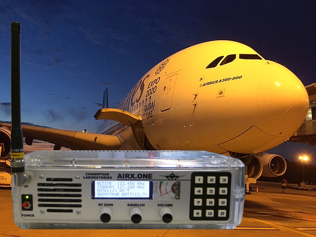


")