 ช้างเผือก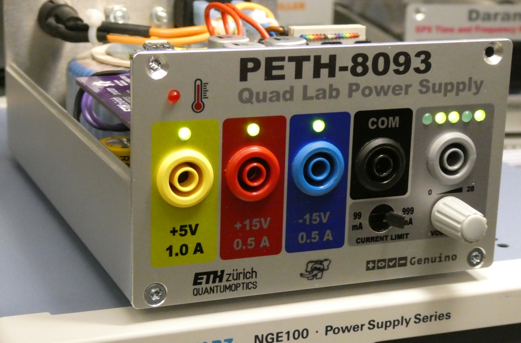
Categories
Statistics
Since 08.08.2014
Counts only, if "DNT = disabled".
216.73.216.203
216.73.216.203
Counts only, if "DNT = disabled".
216.73.216.203
216.73.216.203
Info




เราจะทำแบบวิศวกรผู้ยิ่งใหญ่
15. October 2026
YOUR OPINION •••
average: 0.001, n: 0

When using this form, your ip is stored in order to avoid multiple voting on the same website. That's it.
When using this form, your ip is stored in order to avoid multiple voting on the same website. That's it.
PETH-8093.php 11285 Bytes 13-01-2022 20:10:17
PETH-8093 Power Supply
A compact quadruple Power Supply
✈ The building Blocks • Functional Description
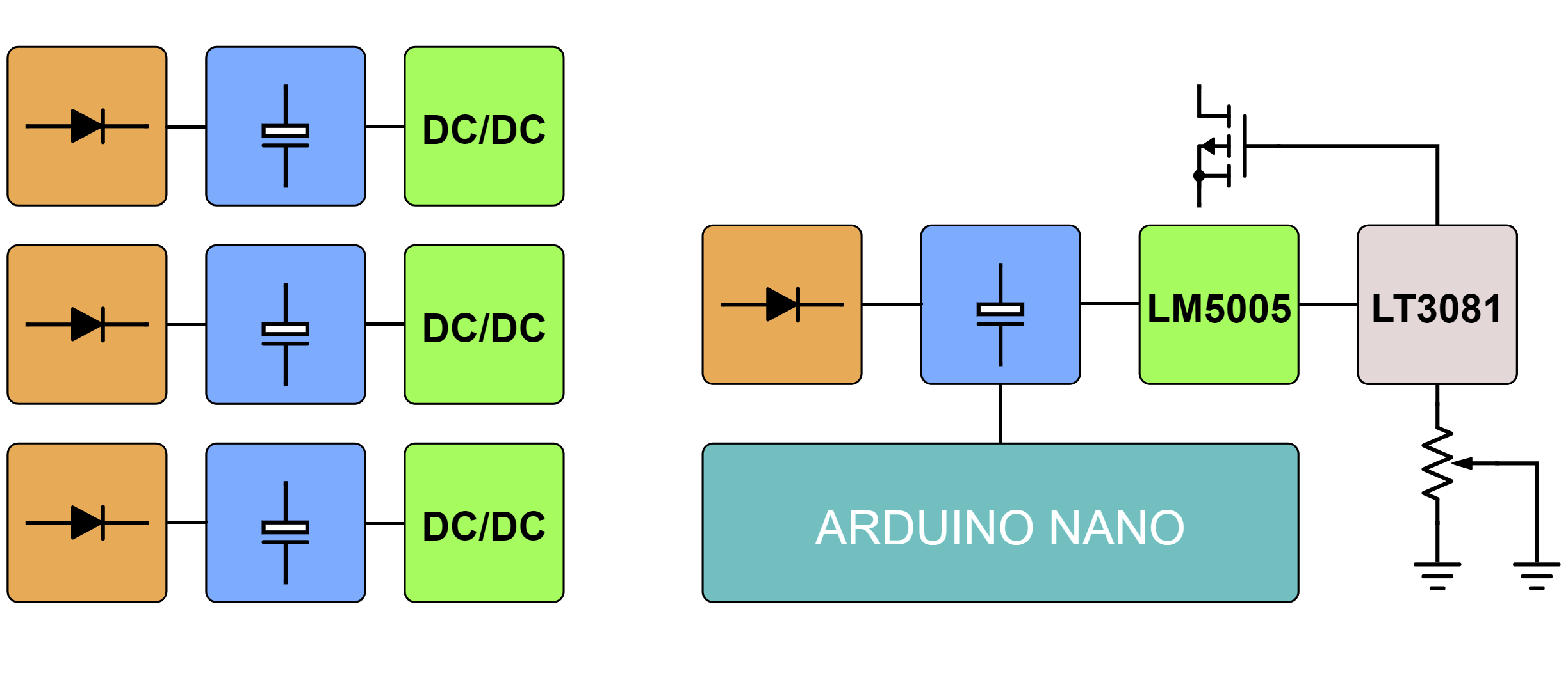
This Power Supply was mainly designed to recycle a bunch of toroid transformers, having worked hard in their previous life in AOM-Controllers. On the bottom board, we therefore find three times a bridge rectifier with a storage capacitor. The only "easy" way to get to "reasonable" voltages was the use of step down converters. We used : TSR 2-2450, TSN 1-24150A and P78E15-1000 or similiar.
On the top board, again, a bridge rectifier with some storage capacitors are placed. As we wanted an adjusteable output voltage, the regulation is a cascade of a step down converter (LM5005MH) which can handle input voltages up to 75 V, followed by a linear regulator (LT3081). The output voltage of the later controls the feedback loop of the step down regulator. By that, the input of the linear regulator is always approx. 2 V above the output voltage. The setpoint is defined by a 20 kΩ Potentiometer, sitting on the bottom board.
Finally, an arduino nano is used to monitor the temperature as well as the output voltage. It is displayed with 5 led's, indicating the voltage in a binary fashion.
✈ Downloads

✈ Arduino Sketch - The Code
Double click on code to select ...
/* //////////////////////////////////////////////////////////////////

  ARDUINO/Genuino Project "PETH-8093", yet another Power Supply
  https://www.changpuak.ch/electronics/PETH-8093.php
  Software Version 1.0
  26.12.2021 by ALEXANDER SSE FRANK
  USES ARDUINO NANO EVERY

////////////////////////////////////////////////////////////////// */


// /////////////////////////////////////////////////////////////
// T E M P E R A T U R E,  1 µA/°C * 5k1 = 5.1 mV/°C
// /////////////////////////////////////////////////////////////

float Temperature = 0.0 ;
const int TempPin = A6 ;
const int TempLEDPin = A4 ;
int Tempomat = 0 ;

void UpdateTemperature()
{
  Temperature = 0.5 * (Temperature + analogRead(TempPin) * 0.9583501) ;
}

// /////////////////////////////////////////////////////////////
// C U R R E N T
// /////////////////////////////////////////////////////////////

float Current = 0.0 ;
const int CurrentPin = A5 ;

void UpdateCurrent()
{
  Current = 0.5 * (Current + analogRead(CurrentPin) * 0.4887585) ;
}

// /////////////////////////////////////////////////////////////
// P R I M A R Y   V O L T A G E
// /////////////////////////////////////////////////////////////

float Primary = 0.0 ;
const int PrimVoltPin = A7 ;

void UpdatePrimary()
{
  Primary = 0.5 * (Primary + analogRead(PrimVoltPin) * 0.0782014) ;
}

// /////////////////////////////////////////////////////////////
// S E C O N D A R Y   V O L T A G E
// /////////////////////////////////////////////////////////////

float Output = 0.0 ;
const int OutVoltPin = A0 ;

const int LED1Pin = 6 ;
const int LED2Pin = 5 ;
const int LED3Pin = 4 ;
const int LED4Pin = 3 ;
const int LED5Pin = 2 ;
int Ganz = 0 ;

void UpdateOutput()
{
  Output = 0.5 * (Output + analogRead(OutVoltPin) * 0.0293255) ;

  Ganz = (int)(Output + 0.5) ;
  if((Ganz & 0x01) > 0) digitalWrite (LED1Pin, HIGH ) ;
  else digitalWrite (LED1Pin, LOW ) ;
  if((Ganz & 0x02) > 0) digitalWrite (LED2Pin, HIGH ) ;
  else digitalWrite (LED2Pin, LOW ) ;
  if((Ganz & 0x04) > 0) digitalWrite (LED3Pin, HIGH ) ;
  else digitalWrite (LED3Pin, LOW ) ;
  if((Ganz & 0x08) > 0) digitalWrite (LED4Pin, HIGH ) ;
  else digitalWrite (LED4Pin, LOW ) ;
  if((Ganz & 0x10) > 0) digitalWrite (LED5Pin, HIGH ) ;
  else digitalWrite (LED5Pin, LOW ) ;
}

// /////////////////////////////////////////////////////////////
// S E T U P
// /////////////////////////////////////////////////////////////

void setup()
{
  Serial.begin(115200) ;

  // INPUTS
  pinMode( CurrentPin , INPUT ) ;
  pinMode( PrimVoltPin, INPUT ) ;
  pinMode( OutVoltPin, INPUT ) ;
  // OUTPUTS
  pinMode( LED1Pin, OUTPUT ) ;
  pinMode( LED2Pin, OUTPUT ) ;
  pinMode( LED3Pin, OUTPUT ) ;
  pinMode( LED4Pin, OUTPUT ) ;
  pinMode( LED5Pin, OUTPUT ) ;
  pinMode( TempLEDPin, OUTPUT ) ;
  digitalWrite (LED1Pin, HIGH ) ;
  digitalWrite (LED2Pin, HIGH ) ;
  digitalWrite (LED3Pin, HIGH ) ;
  digitalWrite (LED4Pin, HIGH ) ;
  digitalWrite (LED5Pin, HIGH ) ;
  digitalWrite (TempLEDPin, HIGH ) ;
  delay(3000) ;
  digitalWrite (LED1Pin, LOW ) ;
  digitalWrite (LED2Pin, LOW ) ;
  digitalWrite (LED3Pin, LOW ) ;
  digitalWrite (LED4Pin, LOW ) ;
  digitalWrite (LED5Pin, LOW ) ;
  digitalWrite (TempLEDPin, LOW ) ;


 }

// /////////////////////////////////////////////////////////////
// M A I N L O O P
// /////////////////////////////////////////////////////////////

void loop()
{
  UpdatePrimary() ; Serial.print(Primary,3) ;
  Serial.print(",") ;
  UpdateOutput() ; Serial.print(Output,3) ;
  Serial.print(",") ;
  UpdateCurrent() ; Serial.print(Current,3) ;
  Serial.print(",") ;
  UpdateTemperature() ; Serial.println(Temperature,3) ;

  Tempomat = millis() % 10000 ; // PWM, F = 0.1 Hz
  if((100*Temperature) > Tempomat) digitalWrite (TempLEDPin, HIGH ) ;
  else digitalWrite (TempLEDPin, LOW ) ;
  delay(50) ;
}

// /////////////////////////////////////////////////////////////
// END OF FILE.
// /////////////////////////////////////////////////////////////
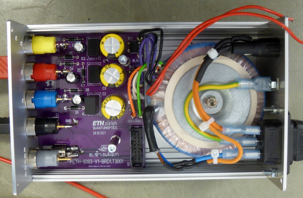
The Bottom Board. Keep it simple was the order of the day ...
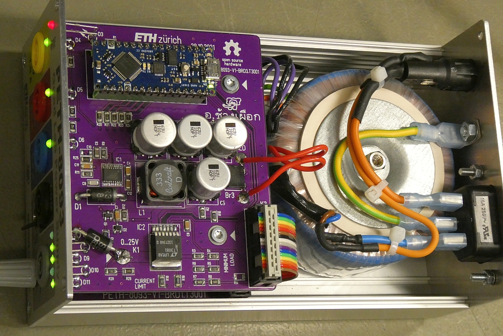
The Top Board. A cascaded approach for the adjusteable voltage is used.
✈ Share your thoughts
The webmaster does not read these comments regularely. Urgent questions should be send via email.
Ads or links to completely uncorrelated things will be removed.
|
t1 = 7399 d
t2 = 231 ms |
★ ★ ★ Copyright © 2006 - 2026 by changpuak.ch ★ ★ ★
|
|


