When using this form, your ip is stored in order to avoid multiple voting on the same website. That's it.
RF-T-DC-Block.php 9017 Bytes 04-03-2025 19:13:25
DC-Block
QO Toolbox 3599 Edition
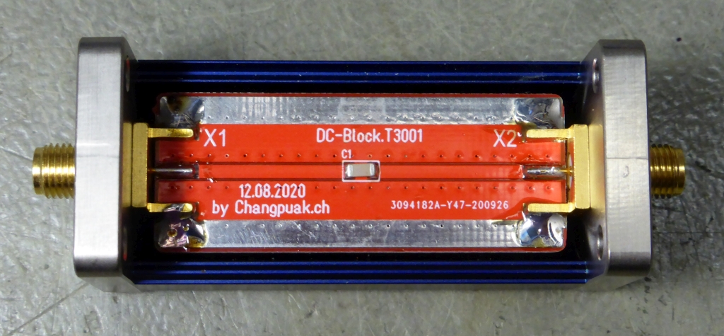
The assembled prototype
✈ Motivation
The available DC-Blocks (from the usual suspects) very often are designed to reach 12.4 GHz or
even more. This at the cost of insufficient low frequency performance. We now can tailor the
DC-Block to the special needs of the experiment.
✈ CP-DC-Block
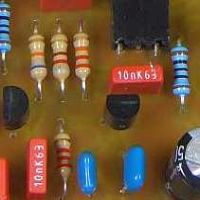
This is the "QO-Kit". A standard Sucobox with SMA Connectors. PCB is made from FR-4.
It can be hacked together in less than an hour. In case you need ultralow cutoff frequency,
assembly may go up to 220 µF, 6.3 V when using 1206 size.
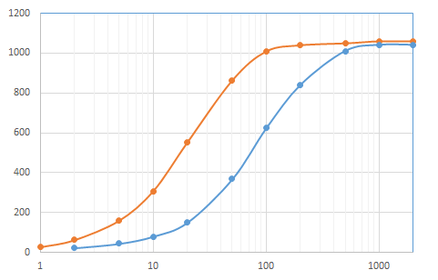
Lower Cutoff, 47 µF and 10 µF3 GHz Span, 47 µF has only 1 dB loss @ 2 GHz
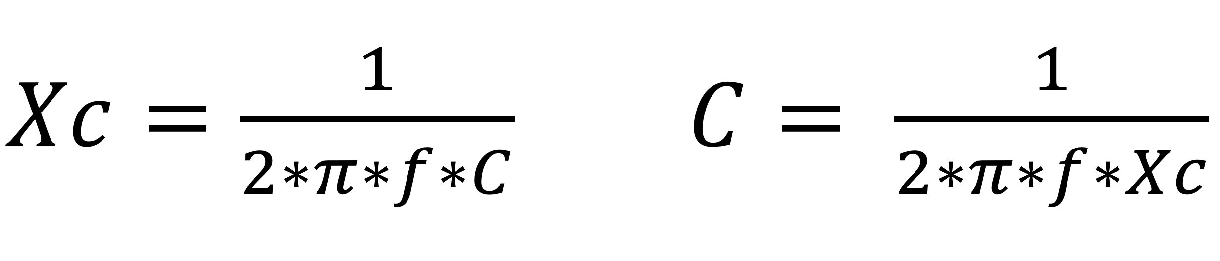
Calculation is super-easy, just keep in mind, that in a 50 Ω System, the two (source and load) resistors
add up, as they are in series. (Therefore choose Xc = 100 Ω)
The so found value for the capacitor is very likely not available. Choose the next larger value
to extend the cutoff frequency to the lower side.
Reactance Calculator
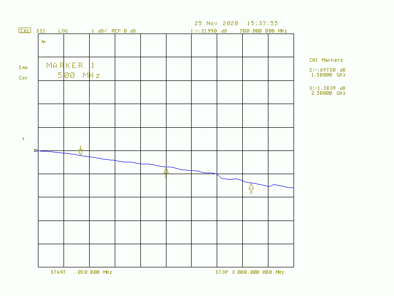
This Capacitor leads to an insertion loss of S21 = 3 dB (or better). Please note, that the matching
S11 is also 3 dB - which is considered poor. Increase the requirement by a factor of 10 i.e.
lower the cutoff frequency to 10 % to have a S21 = 20 dB. This means that only 1 % of the
Power is reflected. This is true when using a 50 Ω system. It is very likely, that
low frequency systems use higher Impedances !
And yes, using the largest value you can get your hands on will yield the lowest possible cutoff frequency.
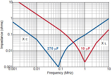
But there is a drawback ! The upper cutoff will decrease, as capacitors are not ideal, meaning
that they start to behave like an inductor, above the self-resonant frequency.
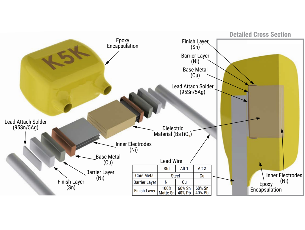
Construction of a (leaded) Capacitor. [1]Impedance vs Frequency. [2]
Source : [1] Drawing courtesy of Kemet, [2] Drawing courtesy of Johanson.
In order to overcome this, nifty Homebuilder use several capacitors in parallel.
See the picture below, the one from the Crystek DC-Block. In case you need ultawide
bandwidth, stack the capacitors on top of each other ...
✈ Mini-Circuits BLK-18-S+
This solution from Mini Circuits reaches 18 GHz (as the name suggests). The datasheet
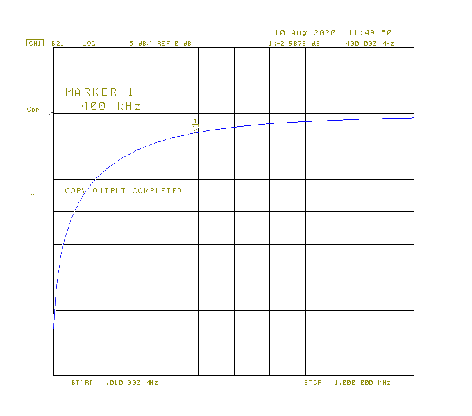
specifies a lower cut-off frequency of 10 MHz. As we all know, MCL specifies very conservative,
and so it does go lower. We measured about 400 kHz or 4.1 nF (on a randomly picked unit). Unfortunately this
is still far away from audio frequency.
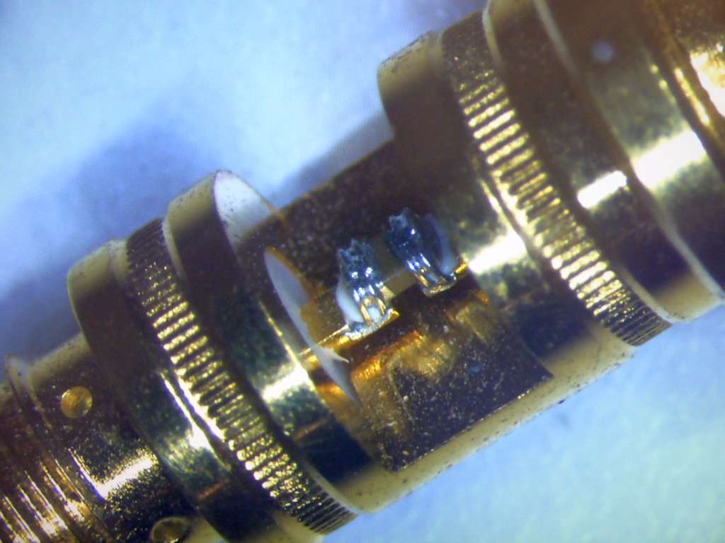
One capacitor, bounded to the inner conductor... has a high lower cut-off
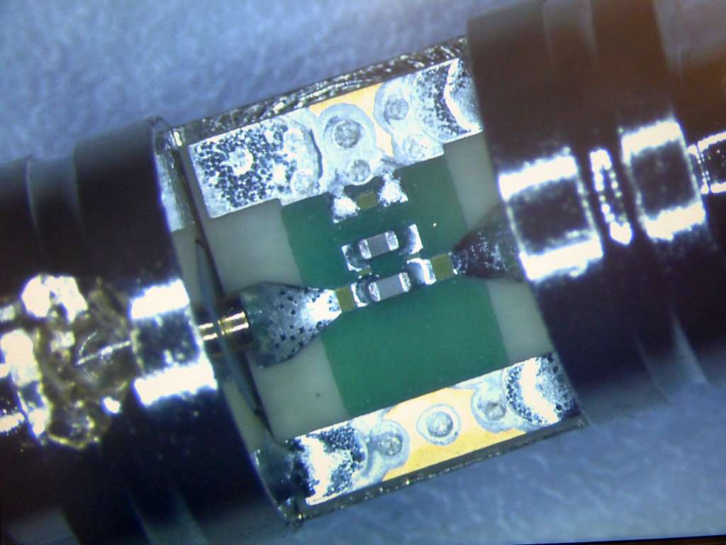
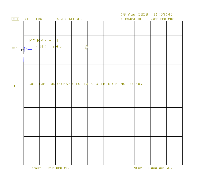
✈ Crystek CBLK-300-30
This solution from Crystek uses a very small pcb with two capacitors (100 nF, 10 nF) in parallel.
The specified maximum frequency is much lower (3 GHz), but also the lower cut-off
frequency and the price. Even so the datasheet speaks of 300 kHz, our measuremnt
shows a much lower frequency.
Two capacitors in parallel, on a pcb... can cover a larger range
✈ Downloads
✈ Share your thoughts
The webmaster does not read these comments regularely. Urgent questions should be send via email.
Ads or links to completely uncorrelated things will be removed.
 ช้างเผือก