 ช้างเผือก
Categories
Statistics
Since 08.08.2014
Counts only, if "DNT = disabled".
216.73.216.253
216.73.216.253
Counts only, if "DNT = disabled".
216.73.216.253
216.73.216.253
Info

เราจะทำแบบวิศวกรผู้ยิ่งใหญ่

27. July 2026
YOUR OPINION •••
average: 5.000, n: 2

When using this form, your ip is stored in order to avoid multiple voting on the same website. That's it.
When using this form, your ip is stored in order to avoid multiple voting on the same website. That's it.
Arduino-Shield-NRVD.php 15995 Bytes 04-03-2025 19:11:02
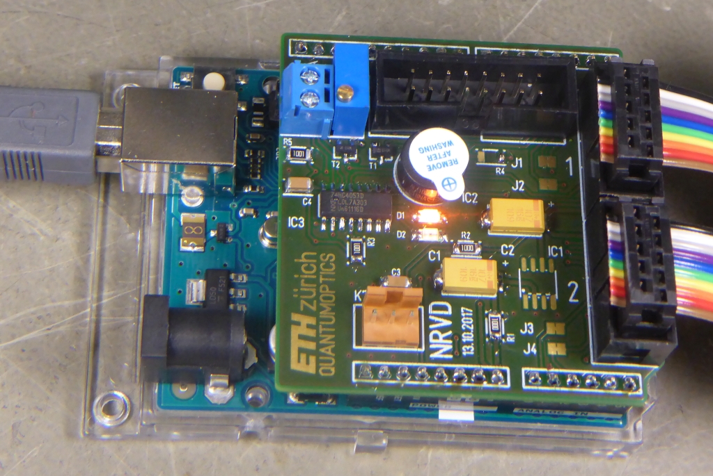
Arduino/Genuino DUAL UHF POWER METER
Shield NRVD, using two ADL5513 (Log Detect/Control.) boards
This design uses twice the ADL5513 (1 MHz to 4 GHz, 80 dB, Log. Detect./Controll.). It mayst be used to measure
S-parameters. It was originally designed to monitor the health status of an antenna (coil) in a vacuum chamber.
If you are a ham, then this is a swr-meter with an external coupler :-)
The complete device in action ...
✈ Vout and Log Conformance vs. Input Power
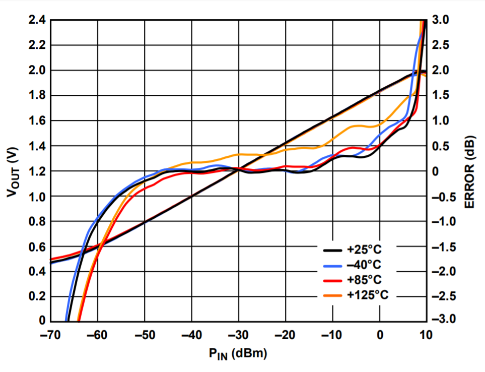 The datasheet of the ADL5513 offers various graphs for output voltages vs. input power at different frequencies. From the graph on the left
we can derive a formula to display the power in dBm as a function of the measured voltage.
The datasheet of the ADL5513 offers various graphs for output voltages vs. input power at different frequencies. From the graph on the left
we can derive a formula to display the power in dBm as a function of the measured voltage.P[dBm] = 50 * U[V] - 90
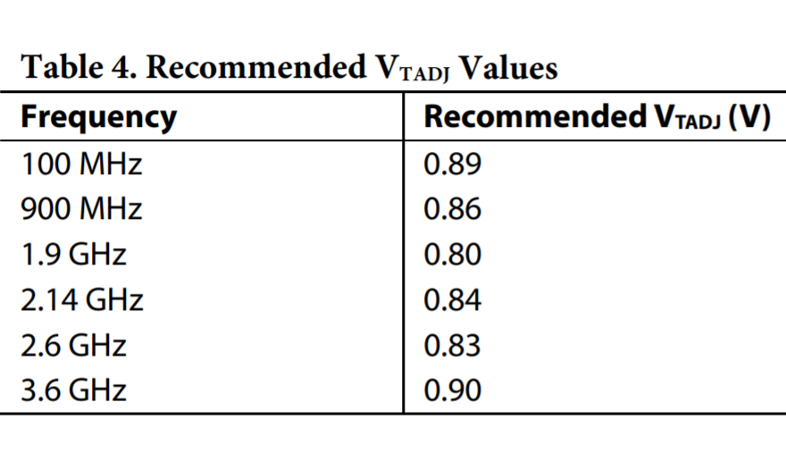 It even offers the possibility to set
a voltage which compensates for a given frequency. From the table to the left, it can be seen, that a formula is not that trivial.
We would rather suggest to use a look-up table, if this compensation feature is to be used over a wider frequency range.
It even offers the possibility to set
a voltage which compensates for a given frequency. From the table to the left, it can be seen, that a formula is not that trivial.
We would rather suggest to use a look-up table, if this compensation feature is to be used over a wider frequency range.Both drawings courtesy of Analog Devices.
✈ The Detection Circuit
The detection circuit has been designed on a single board to allow for universal use. (And quick replacement, if they got toasted).
It consists of an ADL5513 (1 MHz to 4 GHz, 80 dB Logarithmic Detector/Controller), an LTC2400 (24-Bit µPower No Latency ΔΣ™ ADC)
and in order to set for a
compensation voltage, a MAX5381 (Low-Cost, Low-Power, 8-Bit DAC). When you build an SWR meter, the compensation voltage mayst be
set to an average voltage, as we are only interested in differences. The "MainBoard" supplies a highly stable 2.500 V reference
(REF03GSZ) to be used for the LTC2400. The MAX5381 has a built-in voltage reference of 4.0 V and operates from a 5.0 V supply.
And yes, after the photo-shooting, a shielding cover was assembled. (WÜRTH ELEKTRONIK, 36503205)
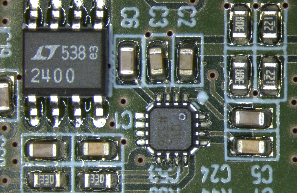
The detction circuit : ADL5513 and a LTC2400 with some 0603
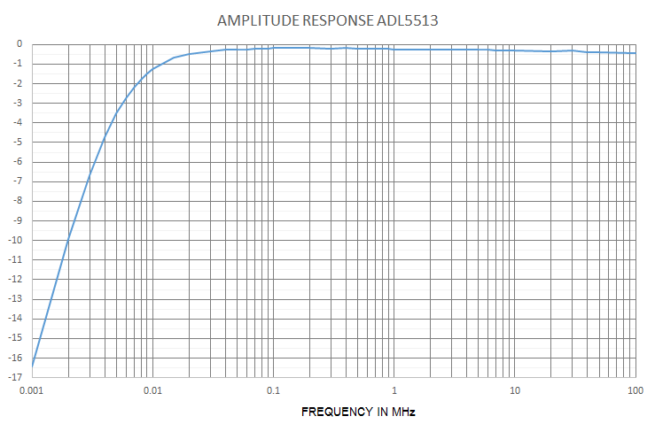
... has a lower cut-off frequency of 5 kHz
✈ Downloads


The Shield "NRVD", the Power Sensors are attached on the right side. R4 depends on your power supply and lcd.
The 2.500 V reference is not yet populated.
✈ Test Sketch for Arduino/Genuino UNO
Double click on code to select ...
/* /////////////////////////////////////////////////////////////
ARDUINO/Genuino (UNO) DUAL UHF POWERMETER
BOARD "NRVD"
Software Version 1.0,
13.10.2017, Alexander C. Frank
//////////////////////////////////////////////////////////////*/

const int beep = 6 ;
const int alarm = 7 ;
const int comp = A0 ;
const int SWITCH = 4 ;
const int data = A1 ;
const int clck = A2 ;
const int CS1 = 2 ;
const int CS2 = 3 ;
const float GAIN1 = 0.92893637 ;
const float GAIN2 = 0.93589236 ;
const float OFFSET1 = -2.40037 ;
const float OFFSET2 = -2.99111 ;

float Power1, Power2 ;

unsigned int TadjCompValue = 255 ;
float TadjCompVoltage = 1.0 ;

#include <Wire.h>
const byte MAX5381 = 0x64 ;
// MAX 5381 HAS A 4.0 V REFERENCE
// MARKING - ADDRESS
// ADMV   0x60
// ADNB   0x62
// ADNH   0x64
// ADMR   0x66

#include <LiquidCrystal.h>
LiquidCrystal lcd(13, 12, 8, 11, 9, 10);

void setup()
{
  pinMode(SWITCH, OUTPUT);
  pinMode(data, INPUT_PULLUP);
  pinMode(clck, OUTPUT);
  pinMode(CS1, OUTPUT);
  pinMode(CS2, OUTPUT);
  pinMode(comp, INPUT);
  pinMode(beep, OUTPUT);
  pinMode(alarm, OUTPUT);
  digitalWrite(beep, HIGH);
  digitalWrite(alarm, HIGH);
  delay(200);
  digitalWrite(beep, LOW);
  digitalWrite(alarm, LOW);

  Serial.begin(9600);
  Wire.begin();

  lcd.begin(16, 2);
  lcd.setCursor(0, 0); lcd.print("NRVD DUAL UHF");
  lcd.setCursor(0, 1); lcd.print("POWER METER");

  // APPLY Tadj FACTOR

  Write_DC(0, TadjCompValue);
  Write_DC(1, TadjCompValue);
  TadjCompVoltage = float(TadjCompValue / 64.0);

  delay(2000);

  lcd.clear();


}

void loop()
{
  digitalWrite(SWITCH, 0);
  Power2 = GAIN2 * Read_RF(0) + OFFSET2 ;
  lcd.setCursor(0, 1); lcd.print("CH2: ");
  if (abs(Power2) < 10) lcd.print(" ");
  if (Power2 > 0.0) lcd.print("+");
  lcd.print(Power2,2);
  lcd.print(" dBm ");
  Serial.print(Power1,2);Serial.print(",");
  delay(250);

  digitalWrite(SWITCH, 1);
  Power1 = GAIN1 * Read_RF(1) + OFFSET1;
  lcd.setCursor(0, 0); lcd.print("CH1: ");
  if (abs(Power1) < 10) lcd.print(" ");
  if (Power2 > 0.0) lcd.print("+");
  lcd.print(Power1,2);
  lcd.print(" dBm ");
  Serial.println(Power2,2);
  delay(250);
}


float Read_RF(unsigned int port)
{
  long RawData = 0x00000000 ;
  float power = -99.0 ;
  long a,b,c,d ;
  // CHIP-SELECT
  if (port == 0){digitalWrite(CS1, LOW); digitalWrite(CS2, HIGH);}
  if (port == 1){digitalWrite(CS2, LOW); digitalWrite(CS1, HIGH);}
  // CHECK IF DATA IS READY - DATA GOES LOW
  // YES WE KNOW, THIS IS DANGEROUS :-)
  while (digitalRead(data) == HIGH ) { delayMicroseconds(10); }
  digitalWrite(clck, LOW);
  a = shiftIn(data, clck, MSBFIRST);
  // Serial.print("a:");Serial.println(a,DEC);
  b = shiftIn(data, clck, MSBFIRST);
  // Serial.print("b:");Serial.println(b,DEC);
  c = shiftIn(data, clck, MSBFIRST);
  // Serial.print("c:");Serial.println(c,DEC);
  d = shiftIn(data, clck, MSBFIRST);
  // Serial.print("d:");Serial.println(d,DEC);
  RawData = (a << 24) | (b << 16) | (c << 8) | d ;
  // BITS 31-28 ARE NOT USED HERE
  RawData = RawData & 0x0FFFFFFF ;
  // BITS 3-0 ARE NOT USED HERE
  RawData = RawData >> 4 ;
  // WE USE A 2.5 V REFERENCE
  // WE USE ONLY 16 BITS
  RawData = RawData >> 8 ;
  // THEREFORE 0xFFFF == 2.5000 V
  power = ( 50 * 2.5000 * RawData / 65535.0 ) - 90.0 ;
  return power ;
}


float Write_DC(unsigned int port, byte value)
{
  digitalWrite(SWITCH, port);
  Wire.beginTransmission(MAX5381);
  Wire.write(value);
  Wire.endTransmission();
  // HINT: THE BOARD HAS A VOLTAGE DIVIDER
  // U = 560 / (1k6 + 560) = 0.259259
  // for a value of 255, this results in
  // a voltage of 1.037 V
}

// /////////////////////////////////////////////////////////////
// END OF FILE.
// /////////////////////////////////////////////////////////////
✈ The Formulae
The Power in dBm as of the voltage reading is :
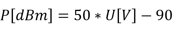
This formula is valid if you use the ADL5513 as shown here.
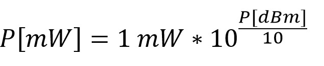
Converted to mW this is :
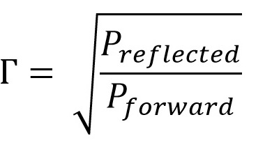
And with that, we can calculate the reflection coefficient:
And finally the SWR or the VSWR is:

E.g. with a Γ of 0.5 we would have a VSWR of ( 1 + 0.5 ) / ( 1 - 0.5 ) = 3 : 1
(Remember these three values .:. open : Γ = 1, short : Γ = -1 and loaded with 50 Ω : Γ = 0)
The Return Loss of a load is the reflection coefficient expressed in dB:
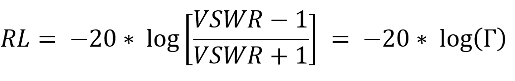
Note: You should always try to have a Return Loss better than 10 dB. Everything above 20 dB is considered "beautiful". And if you have more than 40 dB - we suggest you apply for a job at Hewlett Packard :-)
This formula is valid if you use the ADL5513 as shown here.
Converted to mW this is :
And with that, we can calculate the reflection coefficient:
And finally the SWR or the VSWR is:
E.g. with a Γ of 0.5 we would have a VSWR of ( 1 + 0.5 ) / ( 1 - 0.5 ) = 3 : 1
(Remember these three values .:. open : Γ = 1, short : Γ = -1 and loaded with 50 Ω : Γ = 0)
The Return Loss of a load is the reflection coefficient expressed in dB:
Note: You should always try to have a Return Loss better than 10 dB. Everything above 20 dB is considered "beautiful". And if you have more than 40 dB - we suggest you apply for a job at Hewlett Packard :-)
✈ Share your thoughts
The webmaster does not read these comments regularely. Urgent questions should be send via email.
Ads or links to completely uncorrelated things will be removed.
|
t1 = 7319 d
t2 = 288 ms |
★ ★ ★ Copyright © 2006 - 2026 by changpuak.ch ★ ★ ★
|

|