 ช้างเผือก
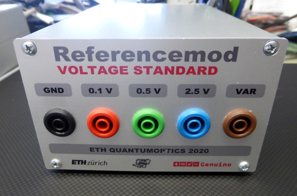
Categories
Statistics
Since 08.08.2014
Counts only, if "DNT = disabled".
216.73.216.253
216.73.216.253
Counts only, if "DNT = disabled".
216.73.216.253
216.73.216.253
Info

เราจะทำแบบวิศวกรผู้ยิ่งใหญ่

27. July 2026
YOUR OPINION •••
average: 0.001, n: 0

When using this form, your ip is stored in order to avoid multiple voting on the same website. That's it.
When using this form, your ip is stored in order to avoid multiple voting on the same website. That's it.
เราจะทำแบบวิศวกรผู้ยิ่งใหญ่
Arduino-Shield-BHUMI.php 16664 Bytes 04-03-2025 19:11:02
Arduino/Genuino Shield 'BHUMI' • REFERENCEMOD
A Voltage Standard with fixed and programmeable outputs
This shield makes a fully functional voltage standard. It uses the LZT100A from Linear
Technology (now Analog Devices). Three fixed outputs (0.1 V, 0.5 V, 2.5 V) as well as a programmeable
output (-10 V ... +10 V) makes this a nifty device for your lab.
✈ Functional Description
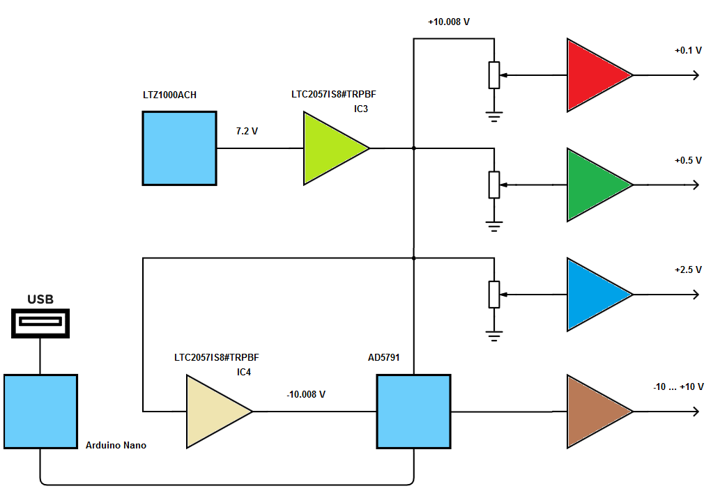
The core of tis design is the LTZ1000ACH from Linear Technology. We used the A version here because it has a significantly higher thermal resistance. It ouputs a highly stable + 7.2 V, which is amplified to have + 10.008 V. This voltage is also inverted to have a - 10.008 V. The operational amplifiers used are LTC2057 because they do not drift and because they can be powered with ±15 V. From the + 10.008 V, the three fixed voltages are derived. They can be adjusted. They are buffered to isolate the (clumsy) user from the critical circuit.
The adjusteable output is realised with an AD5791 (1 ppm, 20-Bit, ±1 LSB INL, Voltage Output DAC). It can swing from - 10 V up to + 10 V. The output is also buffered. In the economy version, this output voltage is defined as a constant in the sketch, the business version allows to control it via the arduino and it's usb connection to the host computer.
The device is powered with a Leomod in order to keep the heat dissipation from the power supply out of the case. The drawing above was done with Scheme-it from Digi-Key.
✈ Inside the LTZ1000ACH
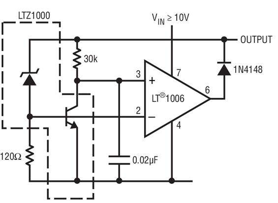
Picture shows building blocks inside the LTZ1000ACH - courtesy of Linear Technology
"The LTZ1000 and LTZ1000A are ultra-stable temperature controllable references. They are designed to provide 7V outputs with temperature drifts of 0.05ppm/°C, about 1.2µVp-p of noise and long-term stability of 2µV/√kHr. Included on the chip is a subsurface zener reference, a heater resistor for temperature stabilisation, and a temperature sensing transistor. External circuitry is used to set operating currents and to temperature stabilise the reference. This allows maximum flexibility and best longterm stability and noise. The LTZ1000 and LTZ1000A references can provide superior performance to older devices such as the LM199, provided that the user implements the heater control and properly manages the thermal layout. To simplify thermal insulation, the LTZ1000A uses a proprietary die attach method to provide significantly higher thermal resistance than the LTZ1000." says the datasheet. We use the LTZ1000ACH here, as it has a high isolation against the surrounding.
✈ Inside the AD5791
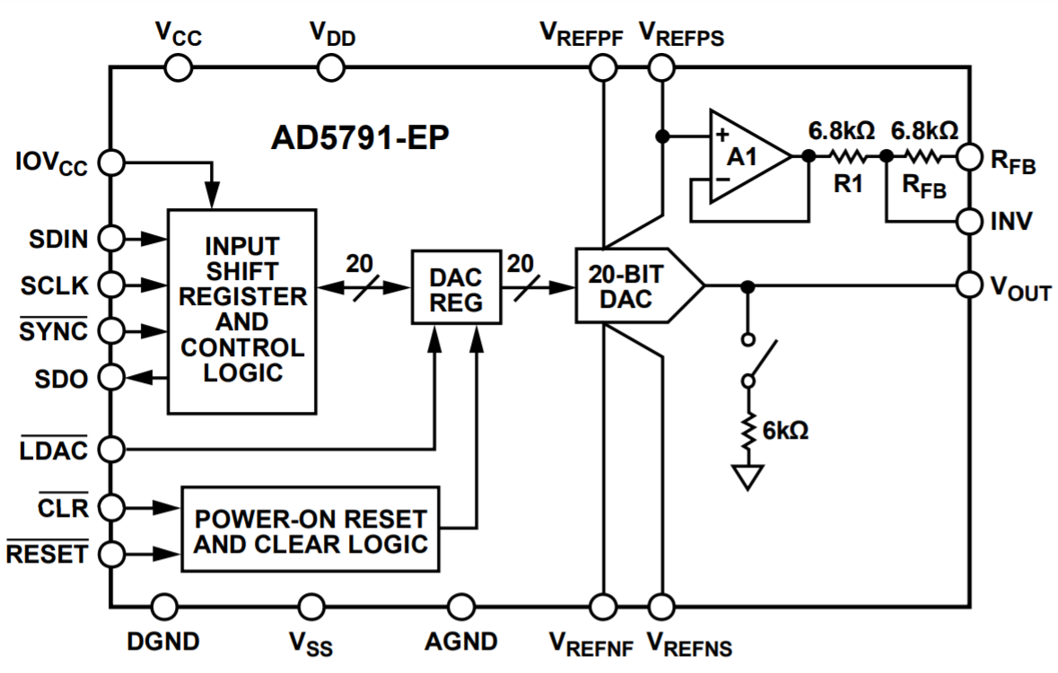
Picture shows building blocks inside the AD5791 - courtesy of Analog Devices
The AD5791 is a high precision, 20-bit DAC with the following features :
• 1 ppm resolution
• 1 ppm INL
• 7.5 nV/√Hz noise spectral density
• 0.19 LSB long-term linearity stability
• <0.05 ppm/°C temperature drift
• 1 µs settling time
• 1.4 nV-sec glitch impulse
• Operating temperature range: −40°C to +125°C
It was used here, because we knew it from yet another Reference Voltage Project and because it is widely bespoken in the Arduino/Genuino™ Community.
✈ Inside the Aluminium Case
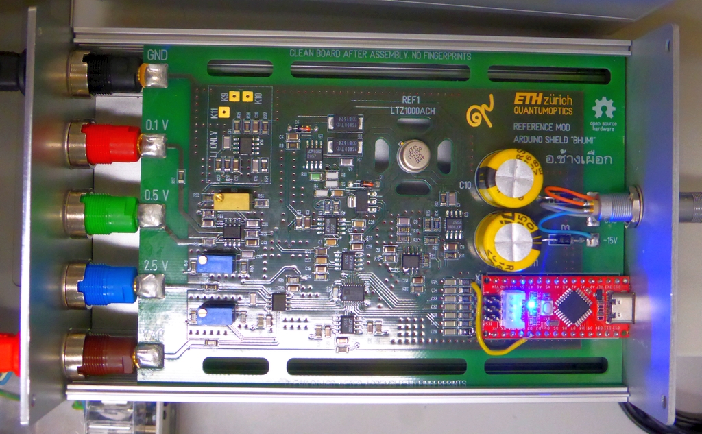
A look inside the case ...
Inside we can clearly spot an Arduino Nano (this time, we used the one from SeeedStudio) as well as the LTZ1000 Voltage Reference. Some No-Drift Opamps as well as a handfull of birdseed make this a nifty voltage reference.
✈ Downloads


✈ Arduino Sketch - The Code
Double click on code to select ...
// /////////////////////////////////////////////////////////////////////
//
// ARDUINO "Seeduino Nano" Sketch for "Referencemod"
// https://www.changpuak.ch/electronics/Arduino-Shield-BHUMI.php
// WRITTEN 05.12.2019 BY ALEXANDER SSE FRANK
//
// Referencemod4.ino
//
// MAYBE HELPFUL :
// https://wiki.analog.com/resources/quick-start/ad5791
//
// /////////////////////////////////////////////////////////////////////


float actVolt = +5.12 ;
float minVolt = -10.008 ;
float maxVolt = +10.008 ;

unsigned long DATA = 60 ;

int SYNC = 2 ;
int SCLK = A5 ;
int SDIN = A4 ;
int SDO = A3 ;
int CLR = A1 ;
int LDAC = A2 ;
int Reset = A0;


void ReMap()
{
  if(actVolt < minVolt) actVolt = minVolt ;
  if(actVolt > maxVolt) actVolt = maxVolt ;
  DATA = 1048575 * ((actVolt - minVolt) / (maxVolt - minVolt)) ;
}


void PulseLDACLow()
{
  digitalWrite(LDAC, LOW) ;
  delay(10) ;
  digitalWrite(LDAC, HIGH) ;
}


void WriteAD5791(unsigned long adr, unsigned long value)
{
  unsigned long PTR = 0x800000 ;
  unsigned long BITS = ((adr & 0x7)<<20)|(value & 0x0FFFFF) ;
  boolean BIT = false ;
  digitalWrite(SYNC, LOW); // START THE WRITE CYCLE
  delay(1);   // SLOW DOWN, WE HAVE AN R-C-LOWPASS
  for (int i=0; i<24; i++)
  {
    BIT = false ;
    if ( (BITS & PTR) > 0 ) BIT = true ;
    digitalWrite(SDIN, BIT);
    // Serial.print(BIT) ;
    delay(1);   // SLOW DOWN, WE HAVE AN R-C-LOWPASS
    digitalWrite(SCLK, HIGH);
    delay(1);   // SLOW DOWN, WE HAVE AN R-C-LOWPASS
    digitalWrite(SCLK, LOW);
    PTR = PTR >> 1 ;
    delay(1);   // SLOW DOWN, WE HAVE AN R-C-LOWPASS
  }
  digitalWrite(SYNC, HIGH);  // STOP THE WRITE CYCLE
  delay(1) ;
  digitalWrite(LDAC, LOW) ;  // SEND LOAD DAC PULSE
  delay(1) ;
  digitalWrite(LDAC, HIGH) ;
  delay(1) ;
  // Serial.println(",") ;
}


void setup()
{
  Serial.begin(115200);
  pinMode(A6, INPUT);
  pinMode(SCLK, OUTPUT);
  pinMode(SDIN, OUTPUT);
  pinMode(SDO, INPUT);
  pinMode(CLR, OUTPUT);
  pinMode(LDAC, OUTPUT);
  pinMode(Reset, OUTPUT);
  pinMode(SYNC, OUTPUT);
  // INITIAL PIN STATES
  digitalWrite(SYNC, HIGH);
  digitalWrite(Reset, HIGH);
  digitalWrite(CLR, HIGH);
  digitalWrite(SCLK, LOW);
  digitalWrite(LDAC, LOW);
  delay(100) ;
  // RESET
  digitalWrite(Reset, LOW);
  delay(10) ;
  digitalWrite(Reset, HIGH);
  delay(10) ;
  // INIT DAC5791
  // THE CONTROL REGISTER
  // Output amplifier configuration control.
  // 0: internal amplifier, A1, is powered up
  // 1: (default) internal amplifier, A1, is powered down
  unsigned long RBUF = 1 << 1 ;
  // Output ground clamp control.
  // 0: DAC output clamp to ground is removed
  // 1: (default) DAC output is clamped to ground
  unsigned long OPGND = 0 << 2 ;
  // DAC tristate control.
  // 0: DAC is in normal operating mode.
  // 1: (default) DAC is in tristate mode
  unsigned long DACTRI = 0 << 3 ;
  // DAC register coding select.
  // 0: (default) DAC register uses twos complement coding.
  // 1: DAC register uses offset binary coding.
  unsigned long BIN2sC = 1 << 4 ;
  // SDO pin enable/disable control.
  // 0: (default) SDO pin is enabled.
  // 1: SDO pin is disabled (tristate).
  unsigned long SDODIS = 0 << 5 ;
  // Linearity error compensation for varying references
  // SEE DATASHEET PAGE 22, WE HAVE 20 VOLTS HERE
  unsigned long LIN_COMP = 0xC << 6 ;
  unsigned long CONTROL = RBUF|OPGND|DACTRI|BIN2sC|SDODIS|LIN_COMP ;
  // CONTROL REGISTER
  WriteAD5791(0x02, CONTROL ) ;
  delay(5) ;
  WriteAD5791(0x02, CONTROL ) ;
  delay(5) ;
  // DATA
  WriteAD5791(0x01, DATA ) ;
}


void loop()
{
  // THIS WILL CREATE A SLOW SAWTOOTH ...

  delay(9000);  // DO NOTHING :-)
  DATA += 512 ;
  if(DATA >= 0xFFFFF) DATA = 0x00000 ;

  WriteAD5791(0x01, DATA ) ;
}


// /////////////////////////////////////////////////////////////////////
// END OF FILE.
// /////////////////////////////////////////////////////////////////////
✈ Power Up • Settling to the final value
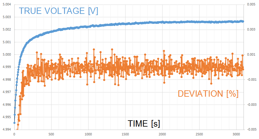
The Output stabilises within minutes. Data is measured with a FLUKE 8846A. Full accuracy is achieved within approx. one hour after power-up. Yes, we know that this is only indicative, but the FLUKE 8846A is the best we have.
✈ Long Term Stability
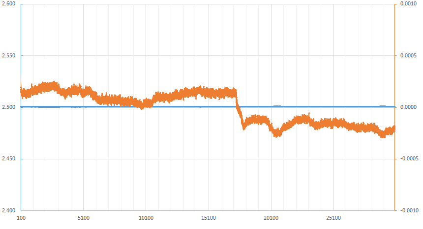
The Output was observed within one week. With a FLUKE 8846A. In the first half, just the Referencemod and the Fluke were running. In the second half, an experiment was started (students in the lab).
✈ Share your thoughts
The webmaster does not read these comments regularely. Urgent questions should be send via email.
Ads or links to completely uncorrelated things will be removed.
|
t1 = 7319 d
t2 = 250 ms |
★ ★ ★ Copyright © 2006 - 2026 by changpuak.ch ★ ★ ★
|

|