 ช้างเผือก
Categories
Statistics
Since 08.08.2014
Counts only, if "DNT = disabled".
216.73.216.233
216.73.216.233
Counts only, if "DNT = disabled".
216.73.216.233
216.73.216.233
Info

เราจะทำแบบวิศวกรผู้ยิ่งใหญ่

28. July 2026
YOUR OPINION •••
average: 0.001, n: 0

When using this form, your ip is stored in order to avoid multiple voting on the same website. That's it.
When using this form, your ip is stored in order to avoid multiple voting on the same website. That's it.
Arduino-Diodemod.php 11284 Bytes 04-03-2025 19:11:00
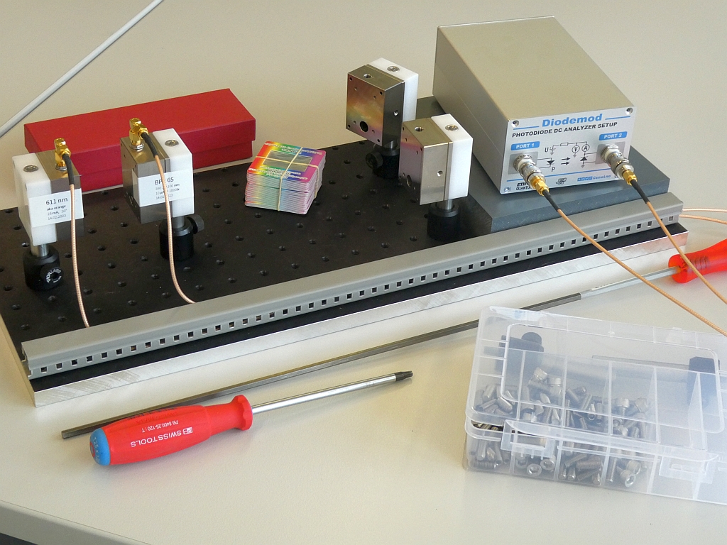
Arduino DC Photodiode Analyzer - 'Diodemod'
A programmable Setup to characterize Photodiodes & Diodes
✈ The building Blocks • Functional Description
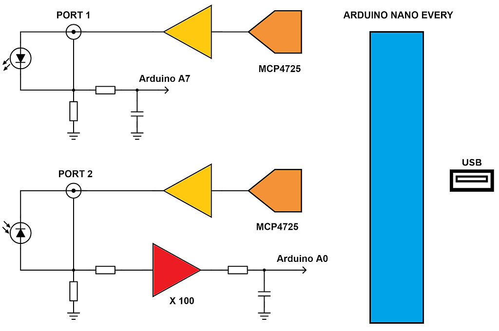
The mastermind of this design is a Python Script which handles the data.
The Diodemod itself holds a voltage source (12 Bit, 10 V, MCP4725) with a current measurement resistor (100 Ω) to supply the LED with a defined Power. The LED is connected to Port 1.
A similiar circuit can be found at Port 2. Here, the photodiode is connected. A reverse Bias voltage can be applied to the DUT (12 Bit, 10 V, MCP4725). The current is measured with 3 resistors (10 kΩ, 100 Ω and 1 Ω) which are selected by a relais. The voltage is amplified by two x10 amplifiers (MAX4238ASA+) which gives an overall amplification by 100.
As we use the ADC of the Arduino (10 Bit), an external Reference (REF02) was added to allow for stable and reliable readings.
✈ Downloads


✈ Characterise Rectifiers - FORWARD @ PORT2
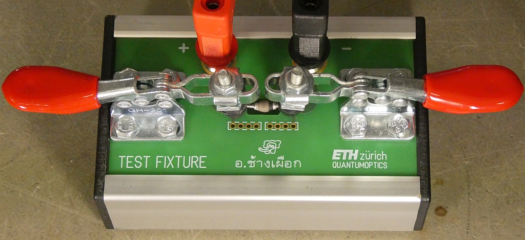
The Voltage was swept in steps of 10 mV. The shunt used was the 1 Ω, as "high" currents were to be expected. The Testfixture used is described here.
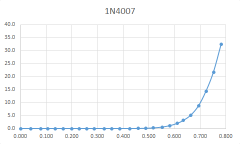
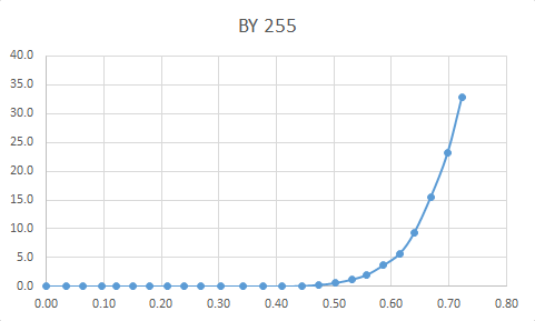
What we always suspected : the Schottkydiode is the more energy efficient choice. And the 1N4007 is the worst. (from our non-representative treasure box pick)
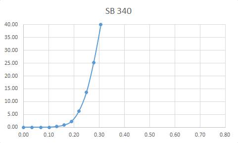
✈ Characterise Photodiodes - FWD @ PORT1, REV @ PORT2
The Voltage was swept from 0.0 V to -5.0 V in 0.5 V steps. Electrical Power of the LED was swept from 0 to 20 mW in 2 mW steps. The distance from the LED (611 nm, 15°) to the Photodiode was 40 mm. With BPX65!, you would get data like this :
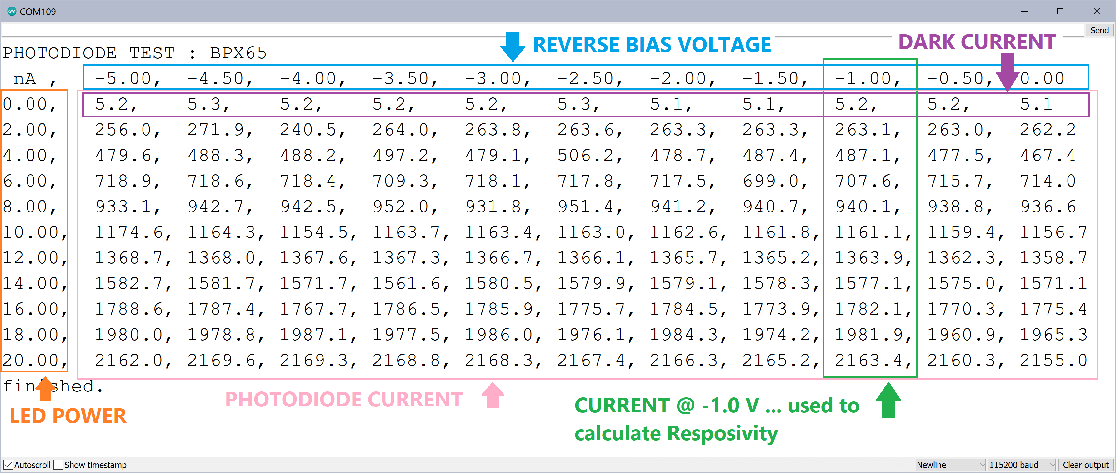
With two columns from the above measurement, we can calculate the Responsivity of the Photodiode. This is just the slope of the curve.
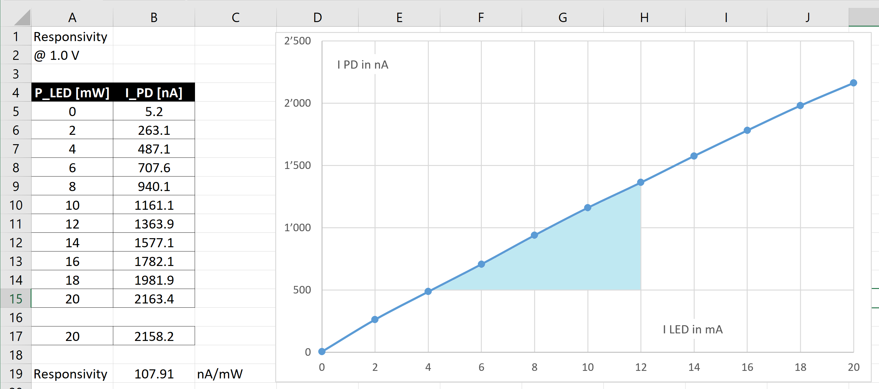

In our case the value is slightly off, as not all Power of the LED hits the Photodiode. For a calibrated setup, it must be determined, how much of the optical power is available at the location of the Photodiode.
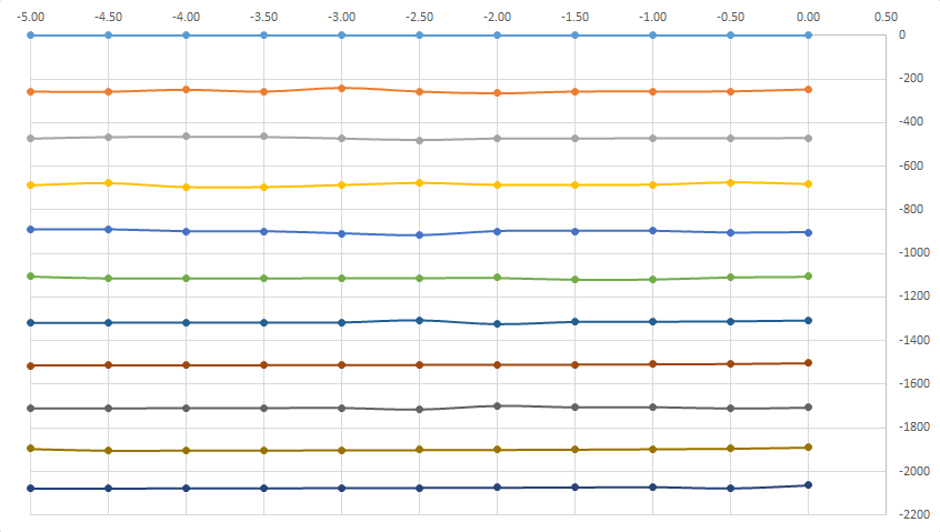
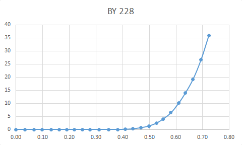
In this second graph, we just entered the measured values from above in an X-Y graph. On the horizontal axe, we see the Bias Voltage, on the vertical axe the current in Nanoampere. The top curve is representing the dark current. The distance from line to line represents a 2 mW increase in Power (LED).
✈ Remote Control of the Diodemod
COM SETTINGS :
Set up the COM port inside the PC according to the following list.
• Baud rate: 115200
• Parity bit: None
• Data bit: 8
• Stop bit: 1
• Data flow control: None
Set up the COM port inside the PC according to the following list.
• Baud rate: 115200
• Parity bit: None
• Data bit: 8
• Stop bit: 1
• Data flow control: None
COMMAND SYNTAX :
*IDN?
Description: Returns the Device's identification.
Example *IDN?
Returns Diodemod 9.0 BY CHANGPUAK.CH
Returns 26.03.2023, ETH QUANTUMOPTICS
SETV1:x.xxx
Description: Sets the Voltage at PORT 1
Example SETV1:9.999
Returns NIL (nothing). Watch out for max Voltage across current Shunt !!!
ILED?
Description: Returns the current measured at Port 1
Example ILED?
Returns 9.5 Unit is mA.
SETP1:x.xxx
Description: Sets the Power at PORT 1. Unit is mW
Example SETP1:10
Returns NIL (nothing). Voltage is ramped up till Power is met.
SETV2:x.xxx
Description: Sets the Reverse Bias at PORT 2. Unit is V
Example SETV2:5.12
Returns NIL (nothing).
SETRNG:x
Description: Sets the Resistor at PORT 2.
Example SETRNG:3
Returns NIL (nothing). 0: all off, 1: 10 kΩ, 2: 100 Ω, 3: 1 Ω. Compliance Voltage < 50 mV.
BY228!
Description: Sweeps Voltage at Port 2 and measures current with 1 Ω shunt.
Example BY228!
Returns a list with Voltage, Current pairs.
BPX65!
Description: Sweeps Voltage at P2 and Power at P1. Measures current with 10 kΩ shunt.
Example BPX65!
Returns a matrix see picture above.
✈ Share your thoughts
The webmaster does not read these comments regularely. Urgent questions should be send via email.
Ads or links to completely uncorrelated things will be removed.
|
t1 = 7320 d
t2 = 3891 ms |
★ ★ ★ Copyright © 2006 - 2026 by changpuak.ch ★ ★ ★
|

|