An FM Stereo Radiostation based on the Si 4713 with RDS
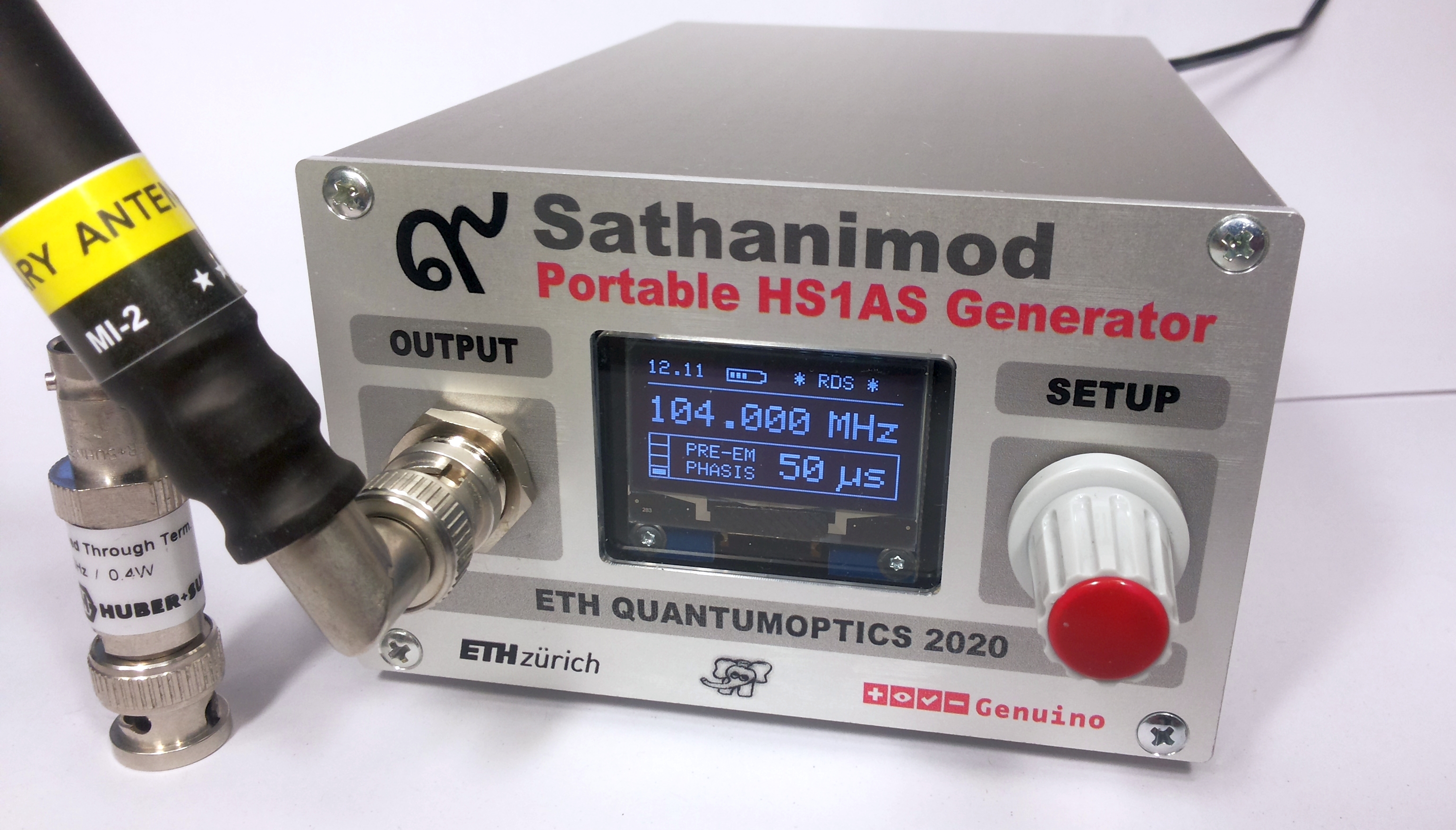
The assembled prototype, sometimes also referred to as portable AOM Controller
✈ Motivation
This project was created to conserve a milestone in radio evolution. Even so it
is superior to DAB, the industry is forcing an "upgrade" [2020]. It is also intended
to commemorise the achievements of "The Great Engineer" who
is sometimes also referred to as "The Majesty of Radio".
โดย อาจารย์ช้างเผือก, พนักงาน มหาวิทยาลัย ของ พ่อ. ETH ซูริค.
✈ Radio Development in Siam
Radio in Thailand was born in the early 1900s on an experimental basis.
Two experimental transmitters were set into service : One in Bangkok
and another on Si Chang Island. Both were used by the Royal Thai Navy for communication with
maritime navigation.
In 1919, King Vajiravudh (Rama VI), used these transmitters to proclaim the birth of broadcasting in Thailand.
The initiator was the ruler of Kamphaengphet, Prince Purachatra Jayagara, who in the early 1920s was also
Minister of Commerce and Telecommunications.
The prince installed a small transmitter in his palace and started experimental broadcasts using his voice
accompanied by classical music. He was so pleased with the result that in 1927 he commissioned his ministry
to carry out further tests.
The first regular transmission was made on May 31st, 1929 when the station 4PJ, bearing the initials of the
prince as the call sign. Located near the Memorial Bridge in Bangkok (Ban Dok Mai Palace, วังบ้านดอกไม้), the transmitter used 200 W
on 8.1 MHz.
Later, a medium wave transmitter of 1 kW was put into service at 937 kHz, call sign 11PJ.
At that time, broadcasting was intended for royalty and these institutions, more than for a general audience.
It was not until September 1929 that the law allowed the public to own radio receivers. Radio Bangkok was
broadcasting from Phyathai Palace.
It was inaugurated on February 25, 1930 to commemorate the coronation of King Prajadhipok (Rama VII).
HM the King delivered the opening address from the Grand Palace and relayed to
Phaya Thai Palace. He announced: "Broadcasting, which has been experimented with in recent years,
is intended to improve education, commerce and entertainment for the public."
This day marks the Birthday of Thai Radio.
From 1931, broadcasting became a state monopoly managed by the Royal Thai government.
Following a coup in 1932 that changed the kingdom into a monarchy constitution, the national radio station
at Phyathai Palace was moved to suburb Bangkok. Radio Bangkok 7PJ has increased its power.
Shortwave tests were also carried out by the transmitter, 8PJ, in order to reach a public international market.
Its original antenna can still be seen at the University of the Armed Forces, near Lumphini Park, Withayu Road.
With World War II looming, services were added in English and French to reach neighboring countries ruled
by Britain and France. Although the original shortwave transmitters near Bangkok used
only 2.5 kW, a new international shortwave service in English was launched on October 20, 1938.
In 1941, the Government launches the construction of a shortwave station in Pathum Thani province north
of Bangkok near Nonthaburi, in the village of Bang Phun. The premises belonged to the Bang Phun public
relations department. The center was equipped with three 10 kW CCA transmitters from Fairburn, Georgia.
The station was reactivated under Thai control in late 1945 with two transmitters bearing the call signs,
HSP2 and HS8PD. Since the end of the Cold War, many Western countries have cut back on their international
services, but not Thailand, which has continued to broadcast over ten hours a day to the world in a dozen
languages. The fleet of transmitters was improved in 1953 with an RCA 50 kW BHF 50, followed
later by a similar BHF (100 kW). In 1985 a 10 kW NEC was installed.
King Bhumibol Adulyadej (Rama IX) was born 1927, about the time his family was pioneering
radio broadcasting in Thailand. So it was no surprise, that he already started in his
youthhood in Lausanne, to experiment with radio construction.
After his return to Thailand in 1952, he set up the Ampone Sathan Throne Station at Dusit Palace (พระราชวังดุสิต).
His aim was to establish a direct link to his people - without the (complicated) royal procedures.
This station consisted of two 100 W communication transmitters from World War II and operated
on 1332 kHz. The station was continuously expanded to 1 kW.
In 1967 the power was increased again, and in 1982 an FM transmitter (104.0 MHz, 5 kW)
was added.
Those transmitters used the callsign HS1AS and proved their usefulness in many emergencies (e.g.
polio epidemic in 1952). In normal operation, it "promotes education, commerce
and entertainment to the general public."
His Majesty produced and moderated a music program every Friday, which also featured well-known musicians
and held jazz sessions with him. He recorded all the pieces himself. The audience could also call and ask
for pieces of music. Although the names of the band members of the "A.S. Band" were never mentioned,
it was no secret that the King himself played the saxophone.
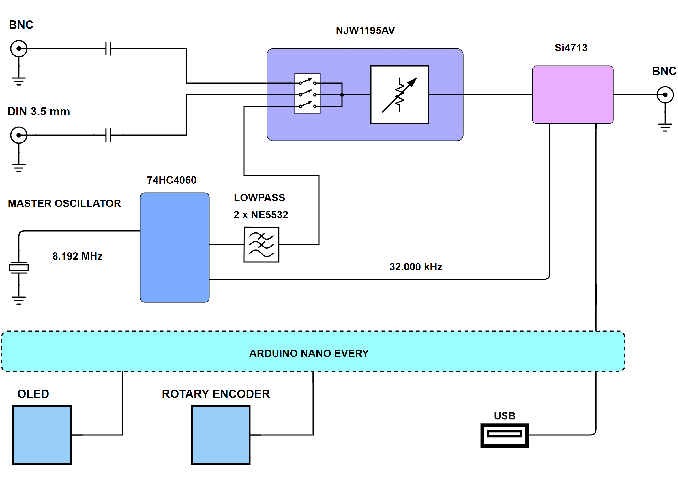
Block Diagram of the Sathanimod - a portable FM Radiostation AOM Controller
Starting at the top left corner, we have two BNC sockets as well as a DIN 3.5 mm input jack. This allows
for external modulation sources, such as an MP3 player or some more sopisticated stuff like the
AFQ100A I/Q Modulation Generator o similiar.
An internal Master Oscillator (8.192 MHz) build around a 74HC4060 synthesises the 32.000 kHz needed
for the PLL in the Si4713 as well as a 400 Hz and a 1 kHz squarewave. The later two are lowpass filtered
to form a sinewave.
All baseband / AF signals are routed to a Matrix build upon a NJW1195AV. This is a 4-channel electronic volume with
4-in 2-out stereo audio selector. It performs low noise and low distortion characteristics with a resistance
ladder circuit. The Gain can be programmed by the Arduino from +31.5 to –95 dB in 0.5 dB steps (and Mute).
The so selected audio frequency is then routed to the Si4713. This is the FM-Radio workhorse, explained
in detail below.
Specifications :
Frequency range
76.0 MHz to 108 MHz
Internal tuning
menu-controlled in 50 kHz steps
Frequency drift
m < 199 Hz / 3 months (Design Goal)
Nominal frequency deviation
68.25 kHz
Class of terminator heating
F3E, stereo and mono
Nominal impedance
50 Ω (Design Goal)
Pilot tone frequency
19 kHz
Pilot tone deviation
0 kHz to 6.75 kHz, adjusteable in 10 Hz steps
DC supply voltage
12 V ±20 %, less than 199 mA
✈ The Workhorse : Si 4713
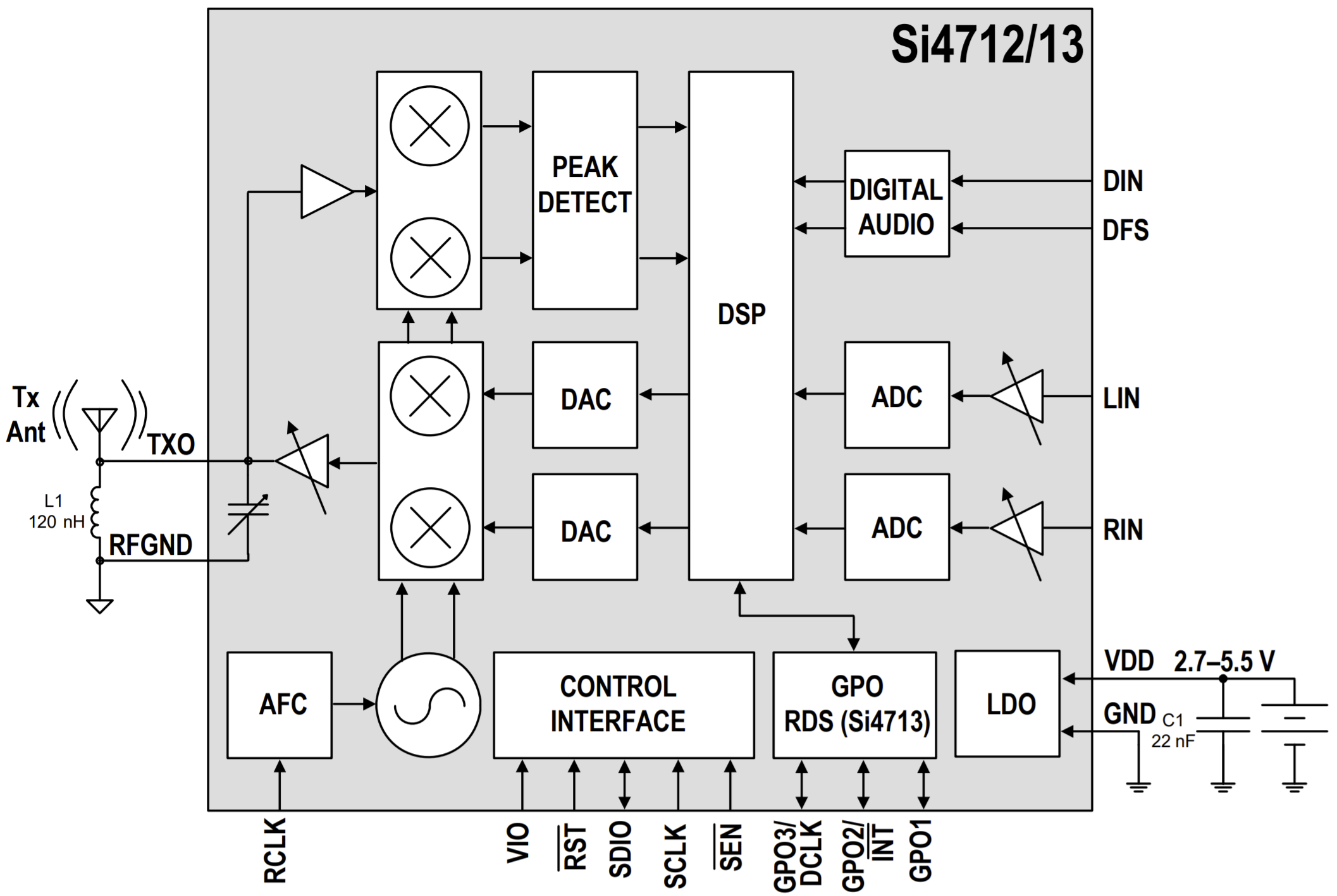
Inside view of the Si4714 - Drawing courtesy of SiLabs
The Si4712/13-B30 integrates the complete transmit functions for standards-compliant
FM broadcast stereo transmission. It offers worldwide FM band support (76–108 MHz) with the
following features :
• Digital stereo Modulator / Advanced modulation control
• Programmable pre-emphasis (50 µs and 75 µs)
• Radio Data System / Radio Broadcast Data System Encoder
• Programmable transmit level
• Frequency Synthesizer with integrated VCO
✈ The PCB, printed circuit board
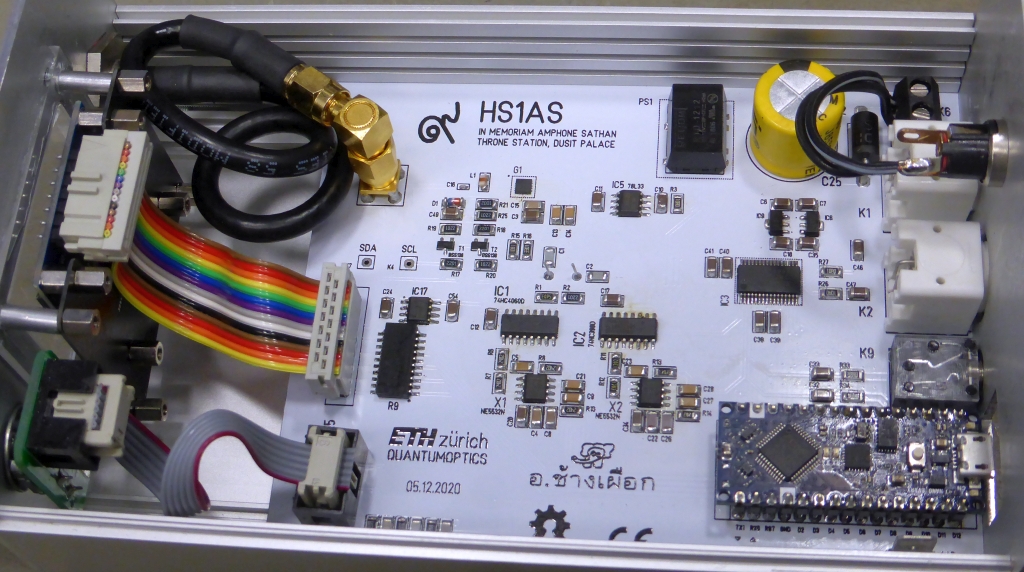
The Printed Circuit Board, inside a KOH4 case
The pcb is a double layered FR4 board, 120 x 100 mm in size. Colour had to be choosen white,
with black silkscreen (as the King passed away already). The only critical (for hand-assembly) component is the
Si4712/13-B30, as it comes in a 3 x 3 mm QFN package with pins even in the corners.
We have routed the traces directly away from the chip, in order to avoid for shorts during assembly.
✈ Downloads
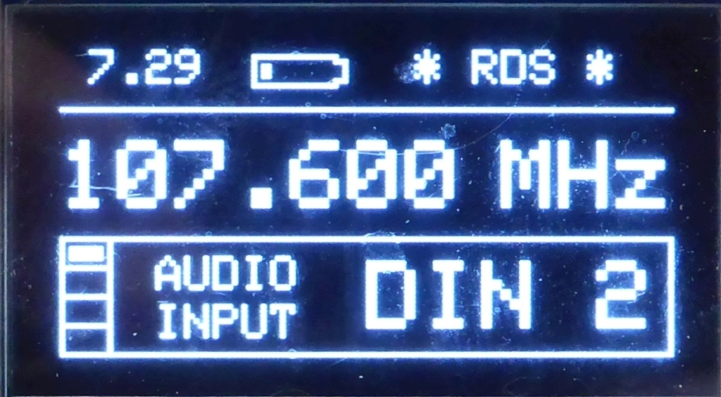
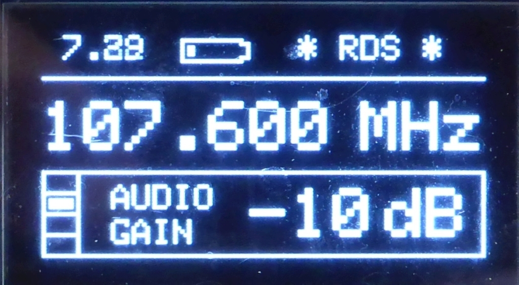
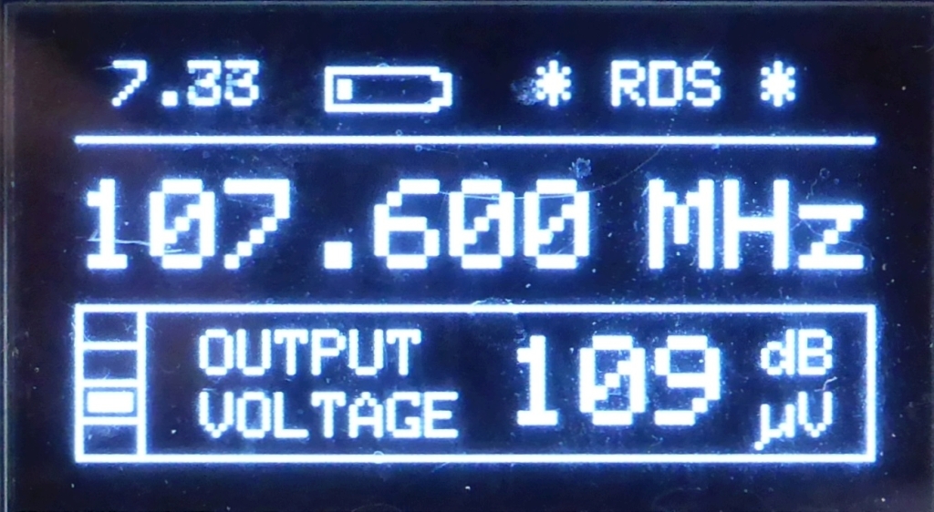
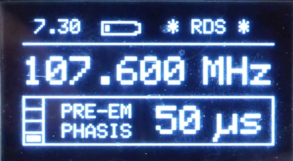
✈ Menu • Settings
AUDIO INPUT : BNC, DIN 3.5 mm, InternalAUDIO GAIN : -95 to +31 dB
OUTPUT VOLTAGE : 88 - 115 dBµVPRE-EMPHASIS : 50 or 75 µs
✈ Performance
Measurement sounds have been used in the past to quantify the quality of a signal path.
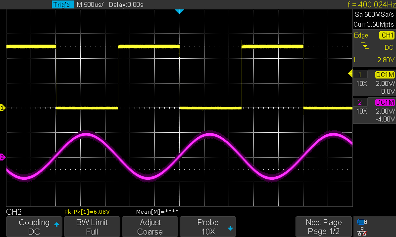
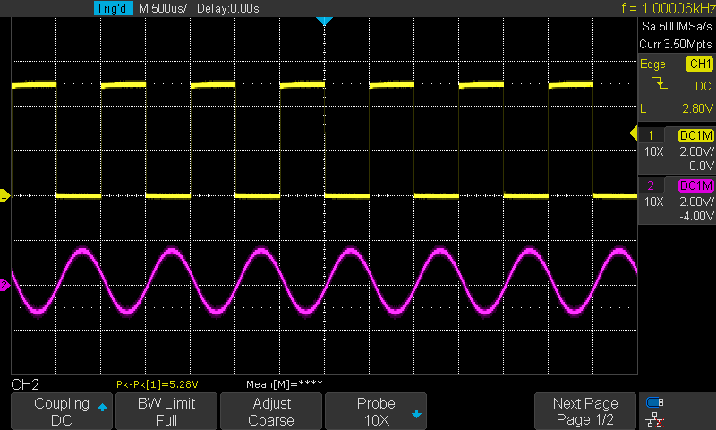
Widely used were 440 Hz, 800 Hz and 1 kHz. From the master oscillator, we derive a
400 Hz as well as a 1 kHz sinewave. By tricky dividing, we first generate a squarewave
with a duty cycle of 50%. This is then lowpass-filtered to get the sinewave.
The lowpass filter used is constructed with two Sallen - Key Lowpassfilters in series
in order to achieve a high spectral purity. Below are the signals measured.
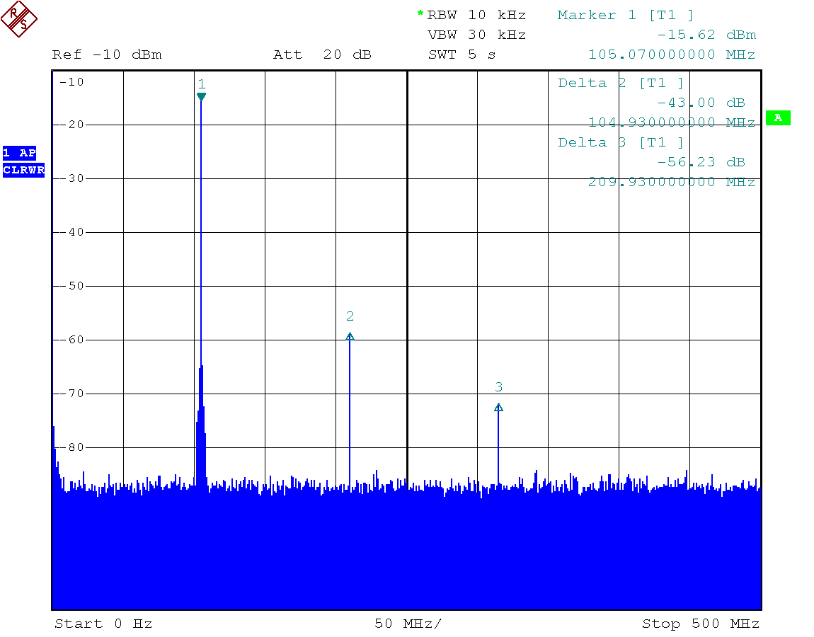
A second important figure would be the generated harmonics. We measured - 43 dBc for a 104.00 MHz carrier.
The output power was set to 115 dBµV, approx. + 8 dBm @ 50 Ω.
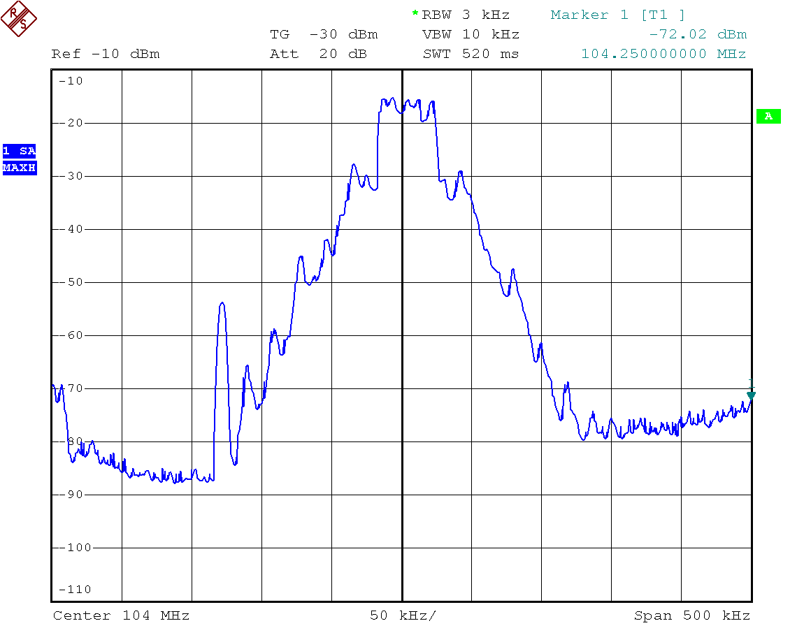
And last but not least, we had a look a the spectrum used of one FM channel. Modulation
source was internal, 400 Hz and 1 kHz. RDS was on. The output power was set to 109 dBµV.
SETTING UP YOUR OWN RADIOSTATION IS NOT WELCOME EVERYWHERE. CHECK LOCAL LAW
BEFORE SWITCHING ANYTHING ON. NOT ONLY MANUFACTURER OF DAB STUFF MAYST NOT BE AMUSED.
✈ Share your thoughts
The webmaster does not read these comments regularely. Urgent questions should be send via email.
Ads or links to completely uncorrelated things will be removed.
 ช้างเผือก