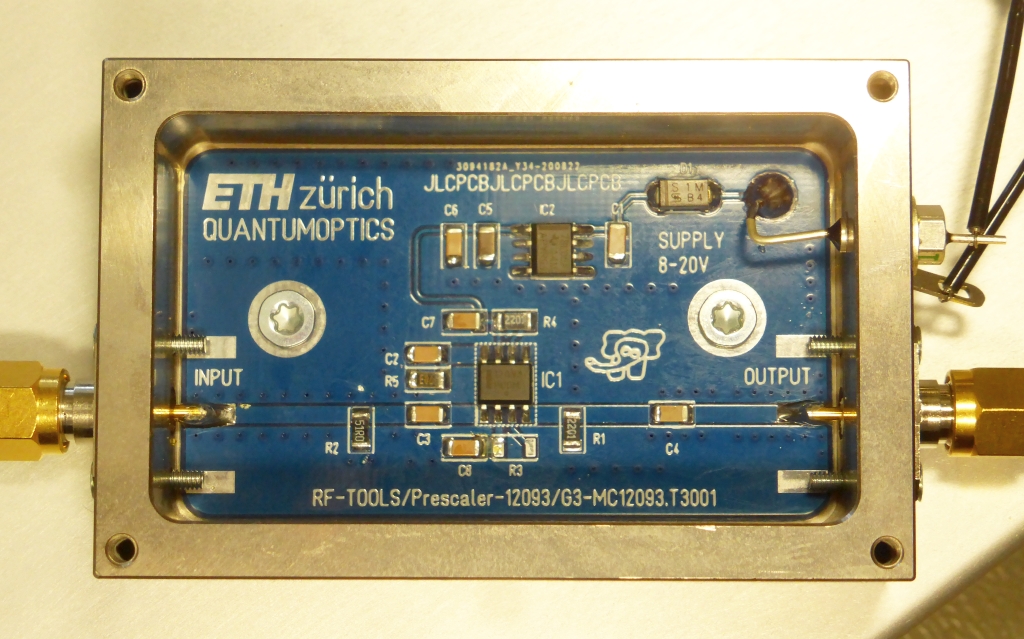
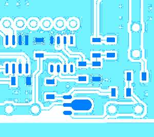
This circuit is that universal, that you always wanted to have one. Even so we
integrated it in many designs, a limited meaurement range of a Microsemi Phase Noise Test Bench
triggered the design of a standalone version.
This standalone prescaler is not very power-hungry (≥ 8 V, 10 mA) and the divider value may be changed by
assembly / disassembly of two different resistors. (:2, :4, :8, see schematics or datasheet)
You may use it to extend the measurement range of many devices, e.g. frequency counters
or to create harmonics and filter out the interesting one.
✈ Downloads
✈ Tendency to Oscillate
The Circuit has an input amplifier with a very high gain, as it has to deal with
signals from -10 dBm up to +10 dBm. Therefore it mayst happen, that the
circuit starts to oscillate, when nothing is connected at the input. If your
setup always has a signal at the input, proceed to next paragraph.
We used a Resistor of 470 kΩ at the unused input to unbalance the working point
of the input amplifier. After the resistor has been added, we measured a DC voltage of
3.40 V and 3.43 V. Tendency to oscillate was reduced drammatically by that.
You may want to reduce the value of the resistor further, at the price of a reduced
sensitivity.
✈ Applications
As with other "handy" things, you may use them for different applications.
It is a well known secret, that the phase noise of an oscillator improves by 3 dB with
every division by two. That's how you build a synthesiser powerful enough to challenge
(and beat) the venerable hp 8640.
Another fact is, that a square wave (which is produced by the digital divider circuit inside)
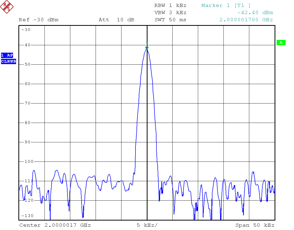
is rich in harmonics. Therefore one could synthesise a frequency by dividing a good quality
crystal oscillator and filter out the desired harmonic.
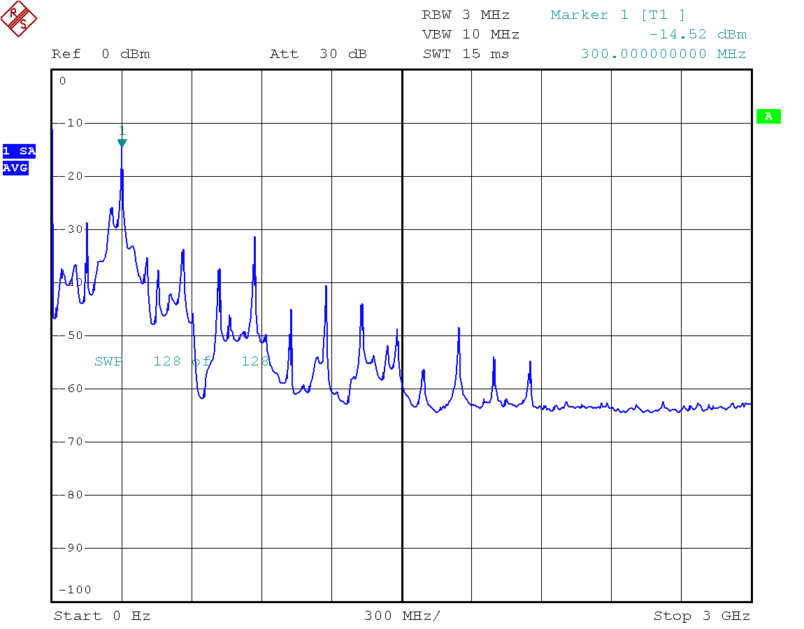
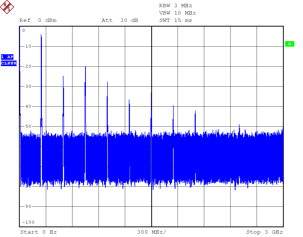
Input 1 GHz, Output n * 250 MHz(Detail) -42 dBm at 2 GHz
Another application is the extension of the Measurement Range of a Phase Noise Test Setup or Frequeny Counter.
[...]
Picture from D goes here :-)
✈ Interfacing with TTL
The output of the Prescaler is slightly too low to be directly connected to TTL circuits. A buffer
with some gain is necessary. The datasheet specifies a typical output voltage of 800 mVpp
up to 350 MHz, decreasing to 450 mVpp at 550 MHz.
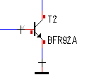
We usually use a Buffer made with a BFR92A (Rc = 360 Ω, Rcb = 3.6 kΩ), capacitively
coupled at the input, dc coupled at the output. Supply is 5 V.
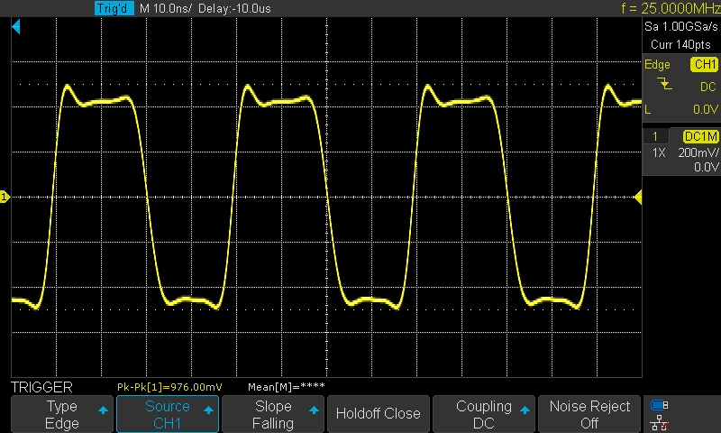
Output at 25 MHz (100 MHz : 4), as seen on a Scope
✈ Share your thoughts
The webmaster does not read these comments regularely. Urgent questions should be send via email.
Ads or links to completely uncorrelated things will be removed.
 ช้างเผือก