 ช้างเผือก
Categories
Statistics
Since 08.08.2014
Counts only, if "DNT = disabled".
216.73.216.253
216.73.216.253
Counts only, if "DNT = disabled".
216.73.216.253
216.73.216.253
Info

เราจะทำแบบวิศวกรผู้ยิ่งใหญ่

27. July 2026
YOUR OPINION •••
average: 0.001, n: 0

When using this form, your ip is stored in order to avoid multiple voting on the same website. That's it.
When using this form, your ip is stored in order to avoid multiple voting on the same website. That's it.
Arduino-Transmod.php 8945 Bytes 20-10-2025 09:16:57
Arduino/Genuino Project Transmod
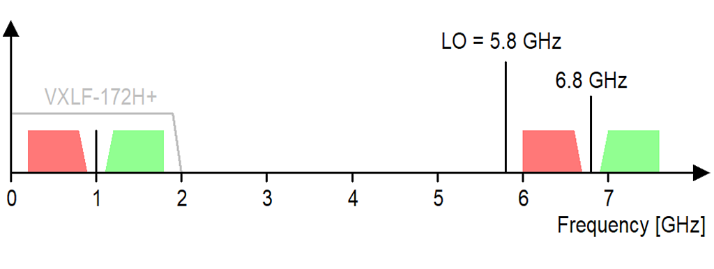
A low noise Downconverter ... 6.8 ± 1 GHz >> 1.0 ± 1 GHz
The final Design in a KOH-4 case.
✈ The Block Diagram / Function Description
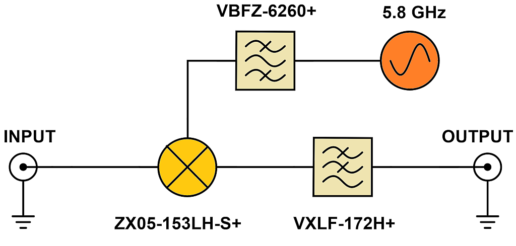
At the Input, we use an N-connector. This is to make sure, that a High Power Attenuator (e.g. BW-N20W50+) can be used.
The design is based around a HMC416LP4E VCO running at 2.9 GHz. The Frequency is stabilized by a ADF4153 PLL. The PLL uses a 100 MHz VCXO, locked to an external 10 MHz signal. (And if no 10 MHz is present, the VCXO is some ppm below 100 MHz).
The LO-signal is doubled by a KC2-36+ (from Mini Circuits) and then passes a Bandpassfilter (VBFZ-6260+).
As the signal level after the doubler was near -20 dBm, we used twice the ZX60-V63+ (each delivering 15.4 dB Gain @ 6GHz).
The now (calculated approx. +10 dBm) is fed to a mixer (ZX05-153LH-S+) @ LO-Port.
At the IF output, a broadband matched Lowpassfilter (VXLF-172H+) is used.
As the Block Diagram suggests ... not much inside :-)
The bright green led indicates that the VCXO is locked to the external 10 MHz. The arrangement of the Mini-Circuits components only deems uncorrelated at first sight :-)
✈ Is the band inverted ?
✈ Downloads


✈ Local Oscillator
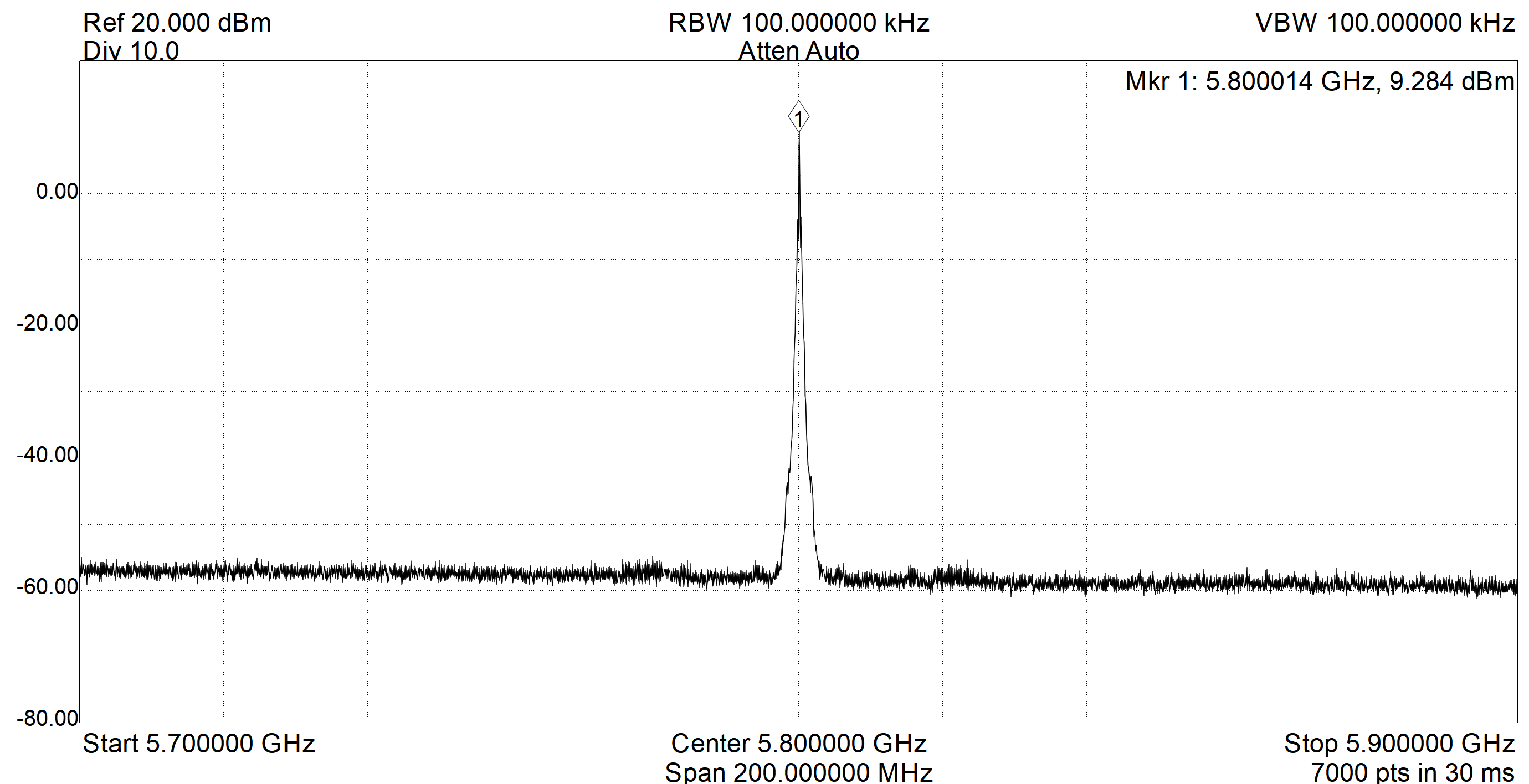
The LO-level (measured with the SA124B — 12.4 GHz Spectrum Analyzer) is +9.3 dBm, very close to the +10 dBm desired by the ZX05-153LH-S+ Mixer.
✈ Output Spectrum
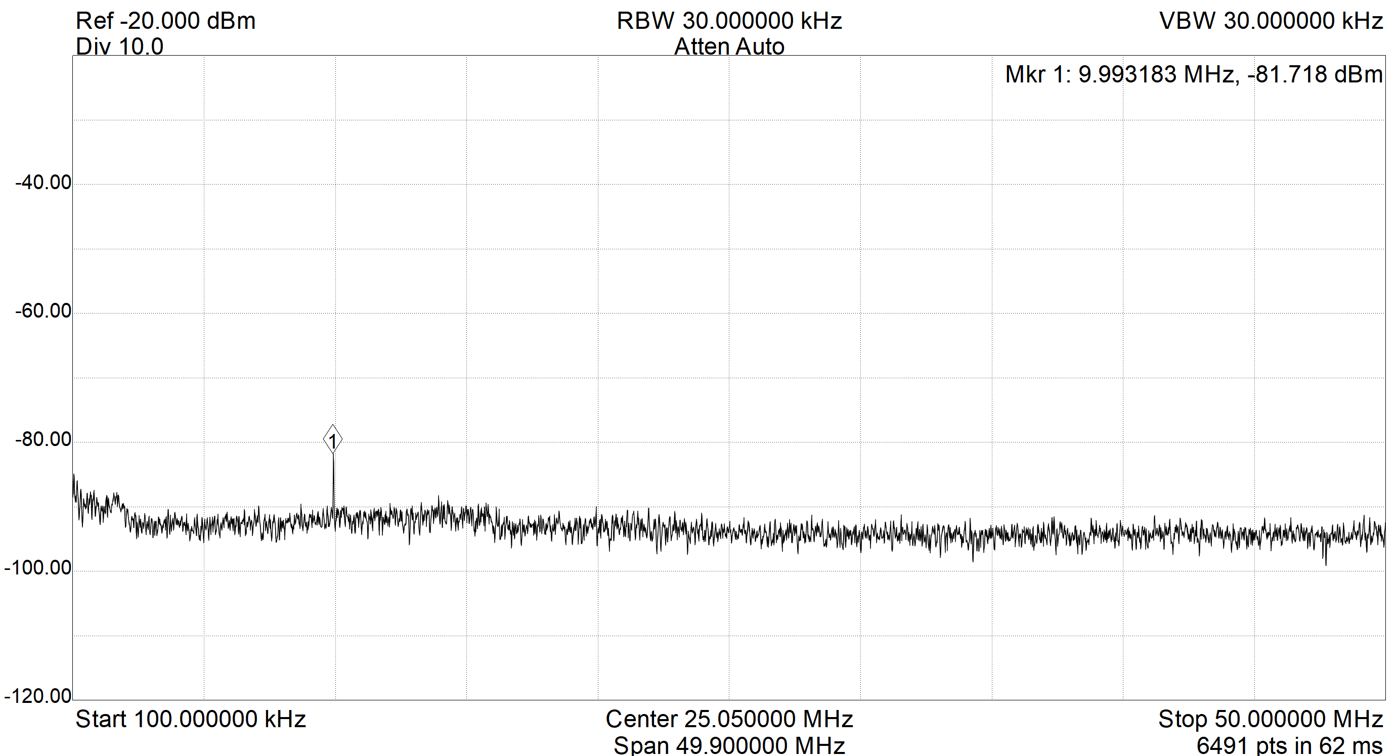
The IF (= Output) Spectrum shows an unwanted spur at 10 MHz. This must be some stray coupling of the external 10 MHz, as the Phase Comparator Frequency of the PLL is 25 MHz. Nothing else observed up to the 2 GHz. The Input (= RF Port) was terminated with 50 Ω.
✈ Conversion Loss
For this measurement, we used a R&S SMB100A
running at - 20 dBm. The IF-Level was recorded with an R&S FSP3 Spectrum Analyzer.
We recorded the following Levels :
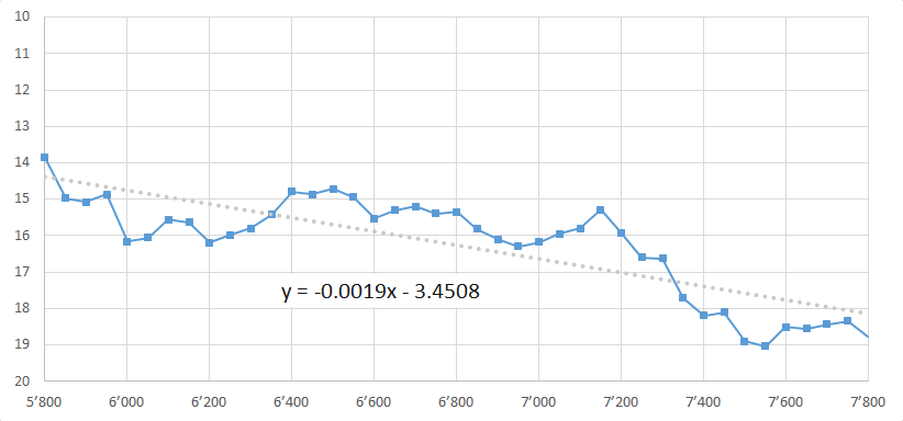
It can be seen, that at those high frequencies, every connector causes losses. All those summed up give an average Insertion Loss of 16.3 dB.
It can be seen, that at those high frequencies, every connector causes losses. All those summed up give an average Insertion Loss of 16.3 dB.
✈ 1-dB Compression Level
For this measurement, we used a R&S SMB100A
running at 6.8 GHz at various levels. The IF-Level was recorded with an R&S FSP3 Spectrum Analyzer.
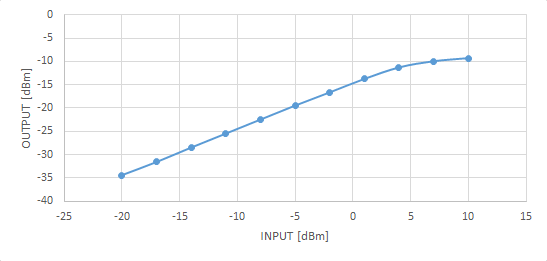
From this measurement, we can define a safe operating level of 0 dBm RF / CW at the input.
From this measurement, we can define a safe operating level of 0 dBm RF / CW at the input.
✈ Remote Control
The Remote Control Functionality of the Transmod is very limited. The Arduino Nano Every outputs just the
Lock-Status of the PLL. Every second it will output the Logic Level of the MUX-Pin of the PLL
by Serial.println(StatusMux, DEC) - which is just zero or one.
✈ Share your thoughts
The webmaster does not read these comments regularely. Urgent questions should be send via email.
Ads or links to completely uncorrelated things will be removed.
|
t1 = 7319 d
t2 = 401 ms |
★ ★ ★ Copyright © 2006 - 2026 by changpuak.ch ★ ★ ★
|

|