 ช้างเผือก
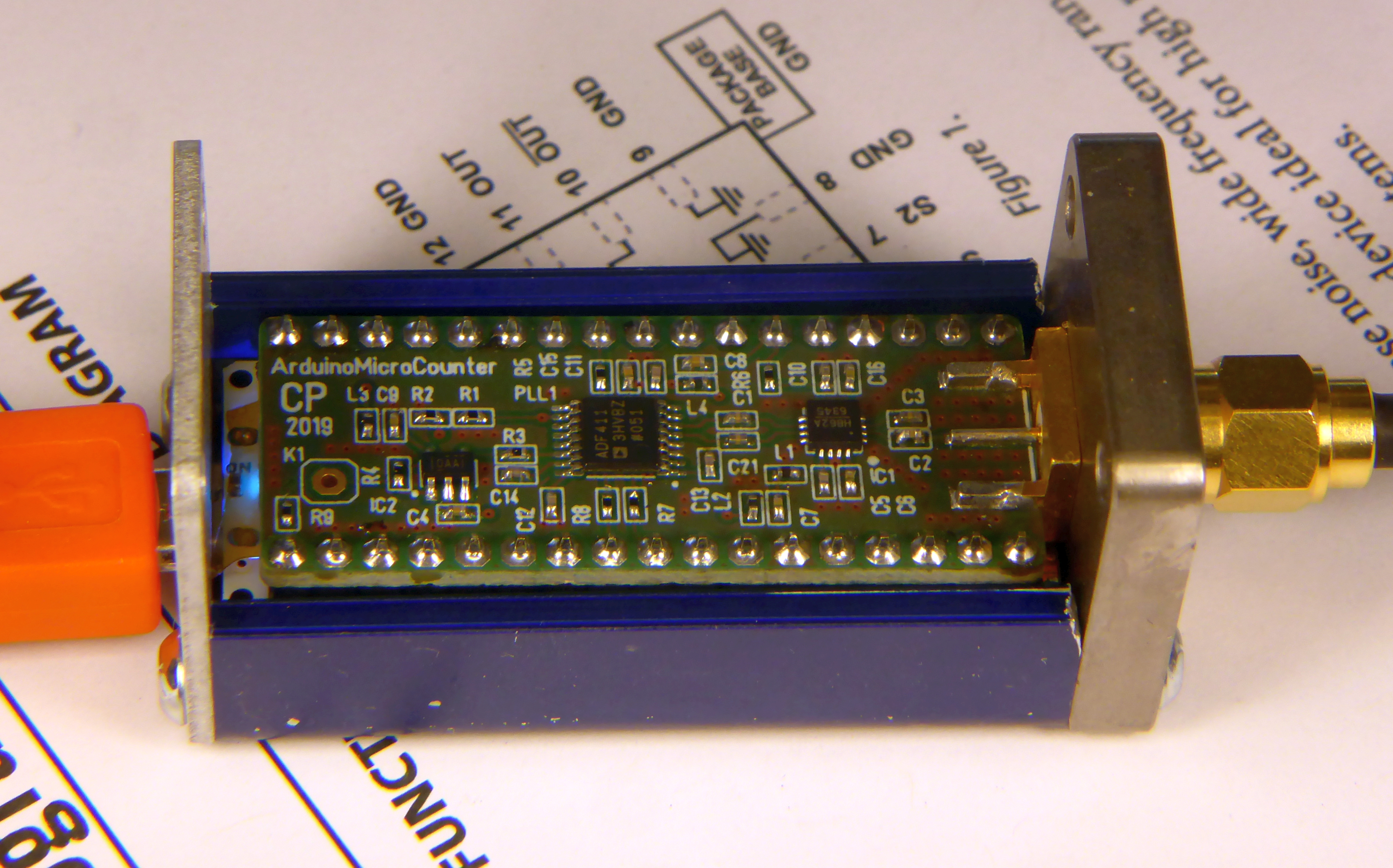
Categories
Statistics
Since 08.08.2014
Counts only, if "DNT = disabled".
216.73.216.253
216.73.216.253
Counts only, if "DNT = disabled".
216.73.216.253
216.73.216.253
Info

เราจะทำแบบวิศวกรผู้ยิ่งใหญ่

27. July 2026
YOUR OPINION •••
average: 9.000, n: 1

When using this form, your ip is stored in order to avoid multiple voting on the same website. That's it.
When using this form, your ip is stored in order to avoid multiple voting on the same website. That's it.
Arduino-24_GHz_Counter.php 14254 Bytes 10-05-2019 10:14:20
Arduino/Genuino 24 GHz Frequency Counter
May be used as a :1000 (or divide by n*8) prescaler as well
The sandwich of our shield and an Arduino Micro in a sucobox
✈ Functional Description
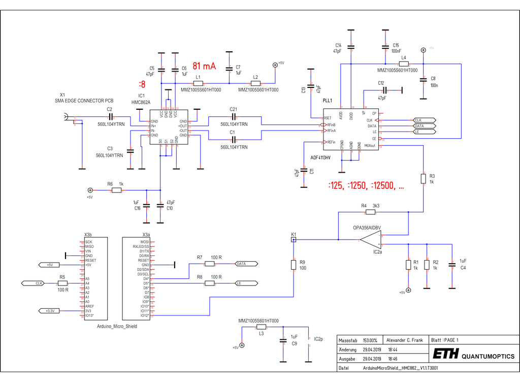
The signal is coupled in via C2, an ultra broadband 100 nF (560L104YTRN) capacitor from American Technical Ceramics. Now the prescaler HMC862 from Analog Devices (who swallowed Hittite) takes care of it. It amplifies the signal and divides it by a factor of eight. It then passes the signal to a pll circuit (ADF4113) which can be programmed to any division value from 3 to 8191 (13-BIT B Counter) and any value from 0 to 63 (6-BIT A Counter). With a prescaler value of 8/9, 16/17, 32/33 or 64/65, the total division range is B * P + A. This is 24 ... 524287 times 8 (prescaler).
We used 0402 components in order to get the desired form-factor, pay respect to the high frequency and to make this a challenging soldering exercise :-)
Finally an Arduino/Genuino Micro does the counting. If the timebase of the Arduino deems unreliable, you can use the divided value to be counted by the counter of your choice. The divided value is available via K1 (MUX_OUT), buffered by a high-speed, voltage-feedback CMOS operational amplifier (OPA356).
The case is a "Sucobox" from Huber & Suhner, Herisau (Switzerland).
And yes, the ISP header as well as the reset-button had to be removed in order to fit in that box.
✈ HMC862ALP3E
"The HMC862A is a low noise, programmeable frequency divider in a 3 mm × 3 mm, leadless, surface-mount package from Analog Devices.
The frequency divider, N, can be programmed to divide from 1, 2, 4, or 8 in the 0.1 GHz to 24 GHz input frequency range.
The low phase noise, wide frequency range, and flexible division ratio make this device ideal for high performance and wideband
communication systems." Says the datasheet. (Analog Devices)
In this design we fixed the value to divide by eight. (By hardware design).
No protection circuit is foreseen. Think twice before using it - and RTFM !
In this design we fixed the value to divide by eight. (By hardware design).
The useful input power range spans from -15 dBm up to + 10 dBm (fIN < 20 GHz).
The useful input power range spans from -5 dBm up to + 10 dBm (fIN abve 20 GHz).
The useful input power range spans from -5 dBm up to + 10 dBm (fIN abve 20 GHz).
No protection circuit is foreseen. Think twice before using it - and RTFM !
✈ ADF4113HV
"The ADF4113HV is an integer-N frequency synthesizer with a
high voltage charge pump (15 V). The synthesizer is designed
for use with voltage controlled oscillators (VCOs) that have
high tuning voltages (up to 15 V). [The charge pump is not used here.]
It consists of a
low noise digital phase frequency detector (PFD), a precision
high voltage charge pump, a programmable reference divider,
programmable A and B counters, and a dual-modulus prescaler
(P/P + 1).
A simple 3-wire interface controls all of the on-chip registers.
The devices operate with a power supply ranging from 2.7 V to
5.5 V and can be powered down when not in use." Says
Analog Devices.
In our circuit, the device is programmed to e.g. 125. Together with the prescaler this gives a division ratio of :1000. But this is only a suggestion. Feel free to program it to any value of your needs.
In our circuit, the device is programmed to e.g. 125. Together with the prescaler this gives a division ratio of :1000. But this is only a suggestion. Feel free to program it to any value of your needs.
✈ Does it really go up to 24 GHz ???
We have no idea :-)
Long answer : This circuit was tested with our 1.1 GHz source (R&S® SMC100A Signal Generator) and it worked nicely, we are currently searching for more advanced test-gear ...
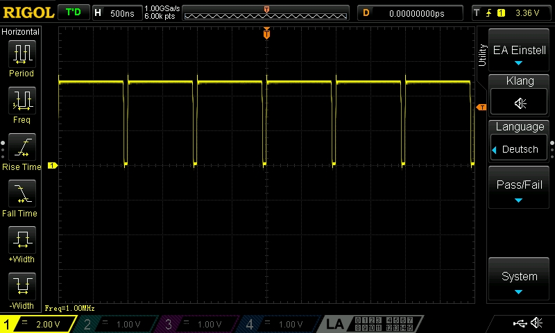
1 MHz (TTL) measured at the output (K1), signal at the input was 1 GHz, 0 dBm
Long answer : This circuit was tested with our 1.1 GHz source (R&S® SMC100A Signal Generator) and it worked nicely, we are currently searching for more advanced test-gear ...
1 MHz (TTL) measured at the output (K1), signal at the input was 1 GHz, 0 dBm
✈ Downloads


✈ Arduino Sketch - The Code
Double click on code to select ...
/* //////////////////////////////////////////////////////////////////
Arduino/Genuino (MICRO) Frequency Counter or Prescaler
https://www.changpuak.ch/electronics/Arduino-24_GHz_Counter.php
Software Version 1.0
01.05.2019 by ALEXANDER SSE FRANK
Uses the  FreqCount Library from PJRC. Download it here :
https://www.pjrc.com/teensy/td_libs_FreqCount.html
////////////////////////////////////////////////////////////////// */


#include <FreqCount.h>
// FIN AT PIN 12 = T1


const int DAT = 4 ;
const int CLK = A4 ;
const int LE = 5 ;
const int INP = 12 ;

const int GateTime = 1000 ;    // ms
unsigned int Divider = 125 ;   // Minimum is 24
// Total Division Ratio is 8 * Divider

unsigned long count ; // FREQUENCY


void setup()
{
pinMode(DAT, OUTPUT);
pinMode(CLK, OUTPUT);
pinMode(LE, OUTPUT);
pinMode(INP, INPUT);
digitalWrite(LE, HIGH) ;
delay(999);
FreqCount.begin(GateTime);
Serial.begin(9600);

ProgAD4113() ;
}

void ProgAD4113()
{
// Divider = N = B*P + A
// 13-BIT B COUNTER, 3 ... 8191
// 6-BIT A COUNTER, 0 ... 63
// PRESCALER VALUE, 8/9, 16/17, 32/33, 64/65
if(Divider < 24) Divider = 24 ; // MINIMUM !!!
long N, B, P, A ;
N = Divider ;
long DataToSend = 0x00000000 ;
byte one, two, tri ;
// ////////////////////////////////////////////////
// REFERENCE COUNTER LATCH (NOT USED)
// ////////////////////////////////////////////////
digitalWrite(LE, LOW) ;
shiftOut(DAT, CLK, MSBFIRST, 0x02) ; // ANTI-BACKLASH PULSE WIDTH
shiftOut(DAT, CLK, MSBFIRST, 0x00) ;
shiftOut(DAT, CLK, MSBFIRST, 0x04) ; // Minimum DIVIDE RATIO is 1
digitalWrite(LE, HIGH) ;
delay(99);
// ////////////////////////////////////////////////
// N COUNTER LATCH
// ////////////////////////////////////////////////
P = 8 ;
if(Divider > 65528)  P = 16 ;
if(Divider > 131056) P = 32 ;
if(Divider > 262112) P = 64 ;
B = N / P ;
A = N - B * P ;
DataToSend = ( B << 8 ) | ( A << 2 ) | 0x01 ;
tri = (( DataToSend >> 0 )  & 0xFF ) ;
two = (( DataToSend >> 8 )  & 0xFF ) ;
one = (( DataToSend >> 16 ) & 0xFF ) ;
digitalWrite(LE, LOW) ;
shiftOut(DAT, CLK, MSBFIRST, one) ;
shiftOut(DAT, CLK, MSBFIRST, two) ;
shiftOut(DAT, CLK, MSBFIRST, tri) ;
digitalWrite(LE, HIGH) ;
delay(99);
// ////////////////////////////////////////////////
// FUNCTION LATCH
// ////////////////////////////////////////////////
switch (P)
{
case 8  :  DataToSend = 0x000022 ;  break;
case 16 :  DataToSend = 0x400022 ;  break;
case 32 :  DataToSend = 0x800022 ;  break;
case 64 :  DataToSend = 0xC00022 ;  break;
}
tri = (( DataToSend >> 0 )  & 0xFF ) ;
two = (( DataToSend >> 8 )  & 0xFF ) ;
one = (( DataToSend >> 16 ) & 0xFF ) ;
digitalWrite(LE, LOW) ;
shiftOut(DAT, CLK, MSBFIRST, one) ;
shiftOut(DAT, CLK, MSBFIRST, two) ;
shiftOut(DAT, CLK, MSBFIRST, tri) ;
digitalWrite(LE, HIGH) ;
delay(99);
}

void loop()
{

if ( FreqCount.available() )
{
count = FreqCount.read() ;
Serial.println(count,DEC) ;
}

delay(99);
}

// /////////////////////////////////////////////////////////////
// END OF FILE.
// /////////////////////////////////////////////////////////////
✈ Assembly
The assembly is done best in a SMD Reflow Oven. Maybe
this pizza oven ?
We assembled the "FUMU" (FUnktionsMUster) with a Weller WAD 101 Lötstation, a WS 81 Lötstation and a Leica MZ6 Microscope. For 0402 components, a magnification of approx. 10 is suggested.
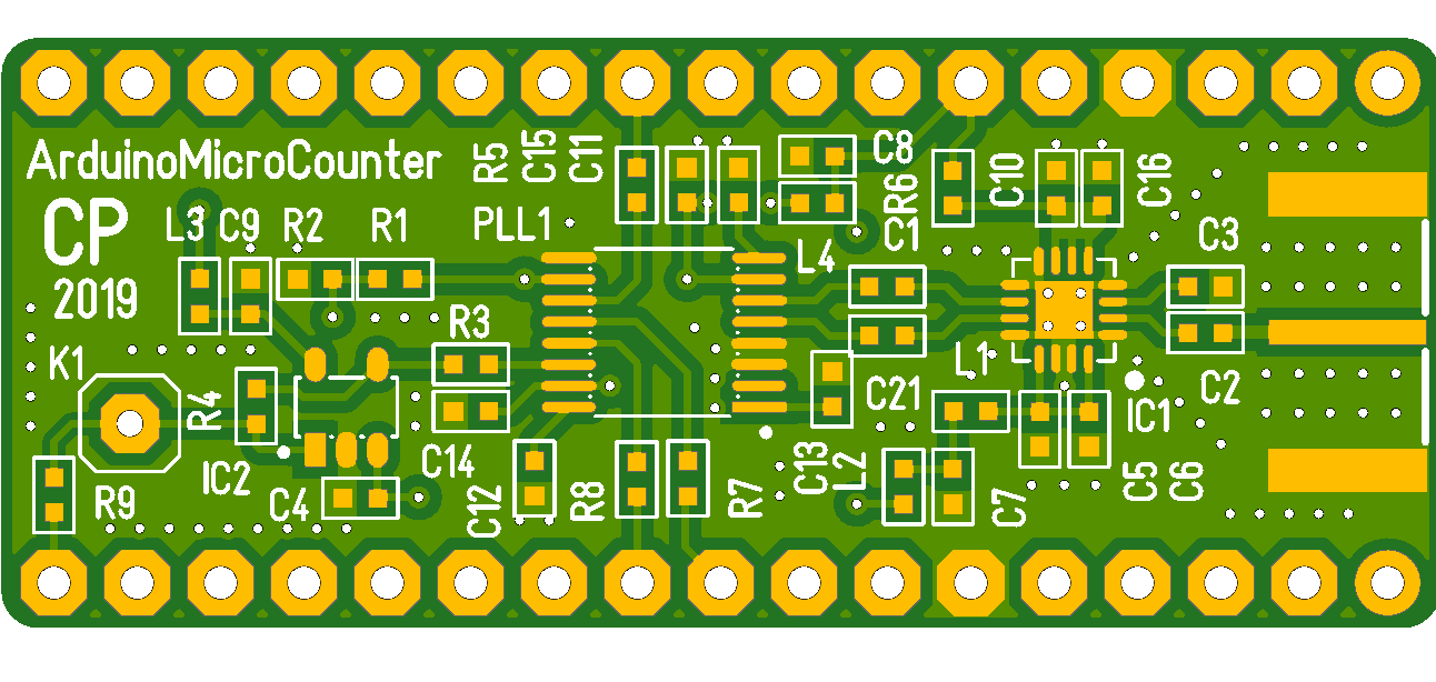 The Printed Circuit Board, Visualisation by Beta Layout
We assembled the "FUMU" (FUnktionsMUster) with a Weller WAD 101 Lötstation, a WS 81 Lötstation and a Leica MZ6 Microscope. For 0402 components, a magnification of approx. 10 is suggested.
✈ Share your thoughts
The webmaster does not read these comments regularely. Urgent questions should be send via email.
Ads or links to completely uncorrelated things will be removed.
|
t1 = 7319 d
t2 = 272 ms |
★ ★ ★ Copyright © 2006 - 2026 by changpuak.ch ★ ★ ★
|

|