This is a final work, an apprentice is doing in our lab. The task was design and assembly of one unit. The time limit was 120 hours to complete (inclusive documentation).
Swiss law demands for a lockdown of the original work, so this text and measurements are
some kind of "Musterlösung" of the webmaster.
✈ Motivation
Physicists tend to shut down everything not in use for 'Security Reasons'.
In the case of a Reference Frequency Standard (distributed in the whole building),
this is suboptimal, if you don't inform your colleagues.
A second scenario (where this circuit is useful) is, if you move a student training
experiment to a lab, which is completely shielded, so the
Daramod
has no chance to see any satellite to lock the 10 MHz VCXO to.
So this is a Security Backup Solution as well as a stand-alone Reference.
✈ The building Blocks • Functional Description
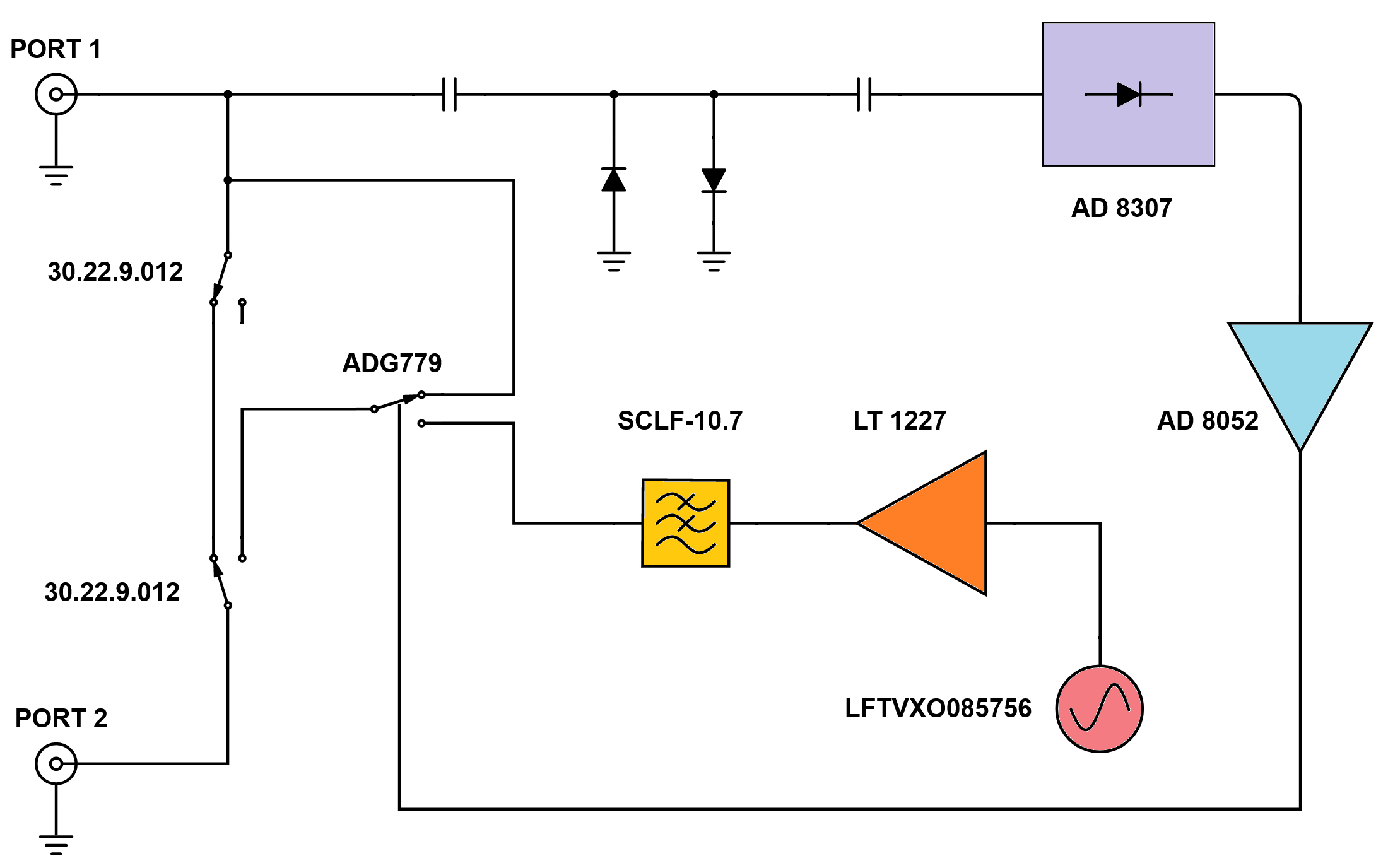
The Level of the GPS disciplined OCXO is constantly monitored by an AD8307 (Low Cost, DC to 500 MHz, 92 dB
Logarithmic Amplifier). Should it drop below the Setpoint (approx. 1.8 V) the ADG779 (CMOS 1.8 V to 5.5 V, 2.5 Ω
SPDT Switch) kicks in and switches the output to the internal LFTVXO085756 (XTAL OSC VCTCXO 10.0000 MHz HCMOS, ±50 ppb)
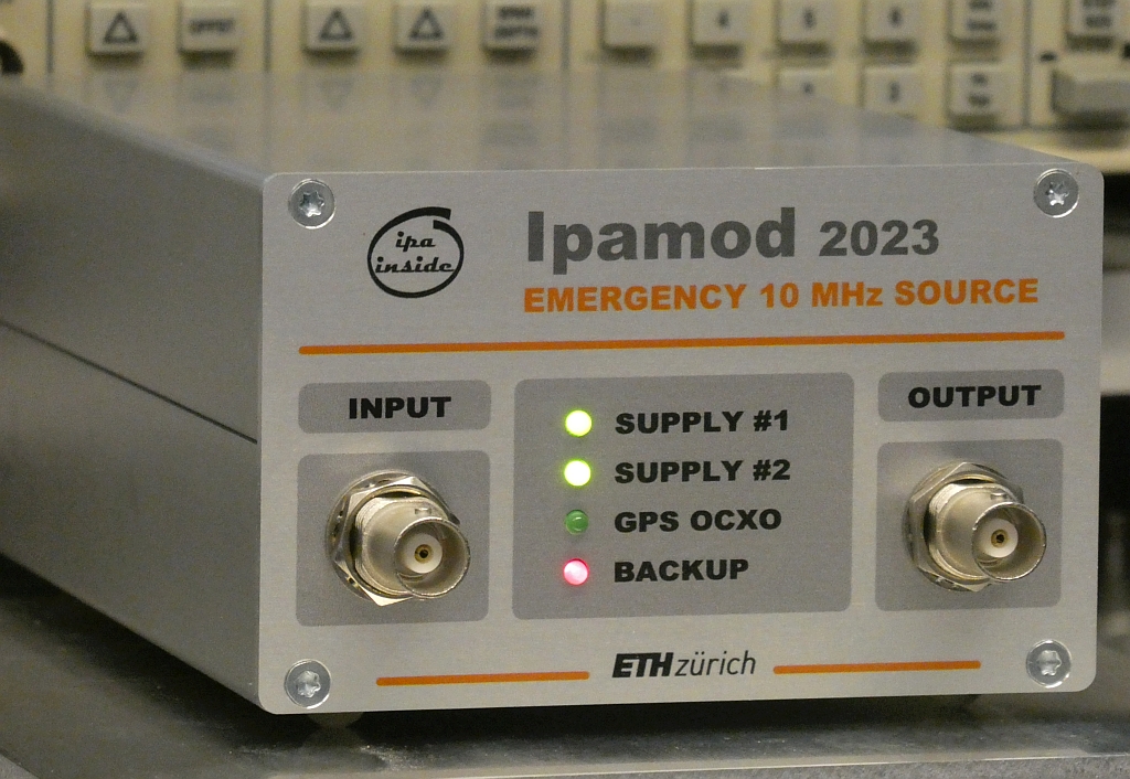
The device can be powered from two independent Power Supplies. Their voltage is indicated by a LED on the frontpanel.
So is the Status of the System. Two more LED's indicate whether the High Precision OCXO is available or
if the Backup Source is in use.
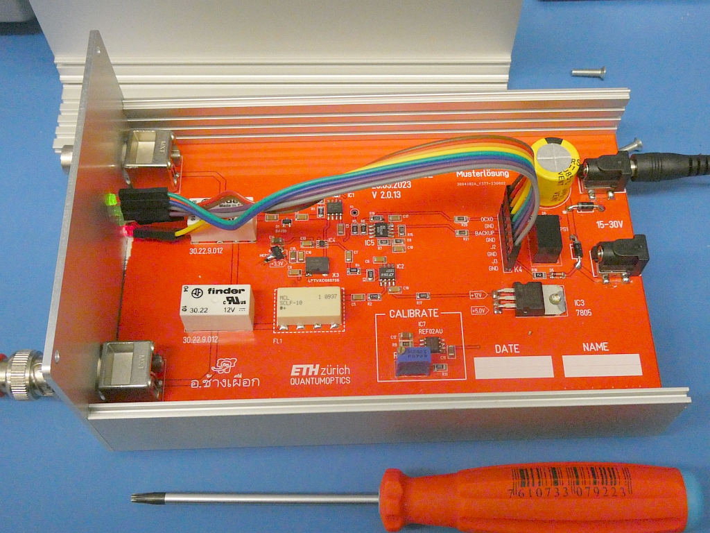
View inside
✈ Downloads
✈ Performance
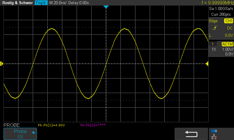
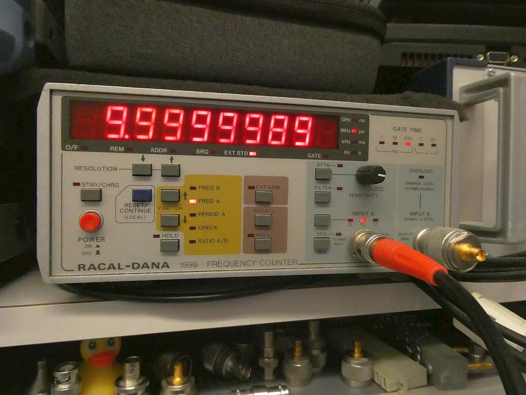
As we used a ±50 ppb TCXO and an Amplifier / Lowpass, the output is close to the
desired 10.000000 MHz. And the lowpass guarantees a pure sinewave.
A pure Sinewave @ 10 MHzThe offset is < 0.1 Hz
✈ Share your thoughts
The webmaster does not read these comments regularely. Urgent questions should be send via email.
Ads or links to completely uncorrelated things will be removed.
 ช้างเผือก