Since 08.08.2014 Counts only, if "DNT = disabled".
216.73.216.233 216.73.216.233
Info
เราจะทำแบบวิศวกรผู้ยิ่งใหญ่
28. July 2026
Hints • Credits • Versions
If the ripple is 0 dB a Butterworth characteristic is calculated.
If the ripple is > 0 dB a Chebyshev bandpass filter is calculated.
The Design procedure follows the Basic routines published by Jerry Hinshaw
and Shahrokh Monem - zadeh in 'Ham Radio Magazine' 01/1985 which are based on a Fortran IV
Program by Rook and Taylor. (1970)
Conversion from Basic to C++ by Dale Heatherington, 05/1996 and finally
to Javascript by Alexander Frank, 01/2014.
In order to verify these calculations / results, it is the best to build a filter and see how it behaves. We decided to
do so and build a bandpass for ADS-B. We wanted to use 3 rods, center-frequency F = 1090 MHz and a bandwidth of B = 10 MHz.
The Designer finally suggests the following values :
Interdigital Bandpass Filter, based on work of Jerry Hinshaw,
Shahrokh Monemzadeh (1985) and Dale Heatherington (1996).
www.changpuak.ch/electronics/interdigital_bandpass_filter_designer.php
Javascript Version : 09. Jan 2014
-------------------------------------------------------------------------
Design data for a 3 section interdigital bandpass filter.
Center Frequency : 1090 MHz
Passband Ripple : 0 dB
System Impedance : 50 Ohm
Cutoff Frequency : 1085 MHz and 1095 MHz
Bandwidth (3dB) : 10 MHz
Fractional Bandwidth : 9.2 MHz
Filter Q : 109
Estimated Qu : 2712.84
Loss, based on this Qu : 0.698 dB
Passband Delay : 63.662 ns
-------------------------------------------------------------------------
Quarter Wavelength : 68.76 mm or 2.707 inch
Length interior Element : 61.15 mm or 2.407 inch
Length of end Element : 61.49 mm or 2.421 inch
Ground plane space : 30 mm or 1.181 inch
Rod Diameter : 8 mm or 0.315 inch
End plate to center of Rod : 15 mm or 0.591 inch
Tap to shorted End : 2.79 mm or 0.110 inch
Impedance end Rod : 88.549 Ohm
Impedance inner Rod : 93.734 Ohm
Impedance ext. line : 50.000 Ohm
-------------------------------------------------------------------------
**** Dimensions, mm (inch) ****
# End to Center Center-Center G[k] Q/Coup
0 0.00 (0.000)
1 15.00 (0.591) 52.41 (2.063) 1.000 0.707
2 67.41 (2.654) 52.41 (2.063) 2.000 0.707
3 119.82 (4.717) 0.00 (0.000) 1.000 1.000
4 134.82 (5.308)
**** Box inside dimensions ****
Height : 68.76 mm or 2.707 inch
Length : 134.82 mm or 5.308 inch
Depth : 30.00 mm or 1.181 inch
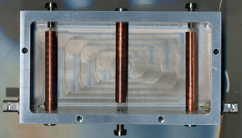
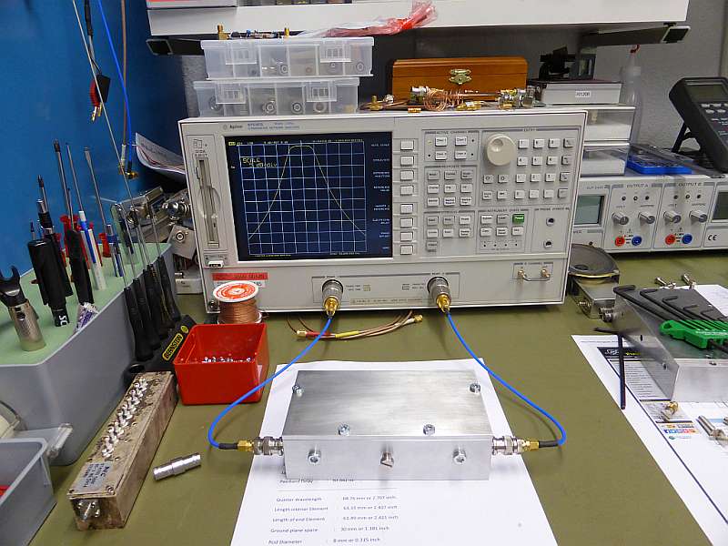
The case was milled from aluminium. The rods are made of copper. No surface coating was applied. Dimension Drawing Case.
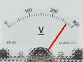
As the rods have been delivered slightly longer (they were all 62.5 mm), the center-frequency was
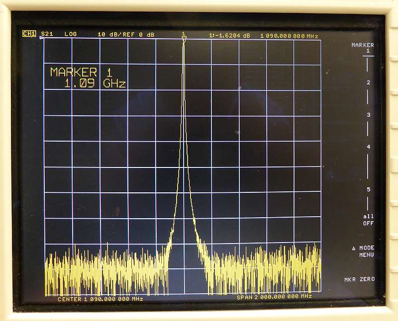
slightly shifted downwards (1070 MHz). See amplitude response. As a a result, we decided to
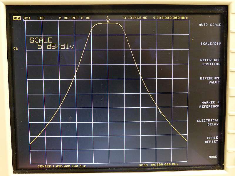
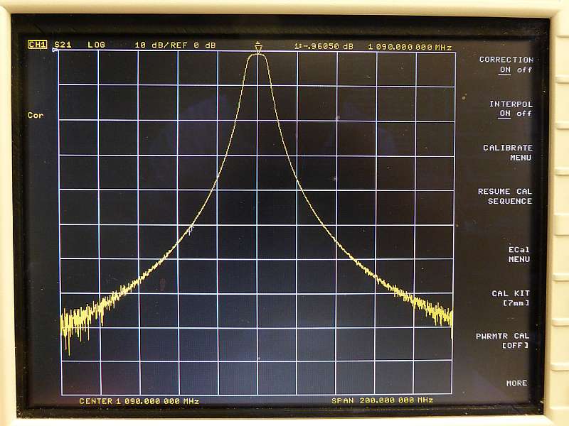
shorten just the middle rod, as the middle tuning screw was fully outside. After having done so, the bandpass developped its full beauty. See pictures
below. (Yes, we know, that photographing the screen is not state of the art). It is to be assumed, that shortening the outer rods lowers
the insertion loss further. It is advantageous to solder the taps before mounting the rods into the case. (heat transfer)
✈ Verifying the results #2
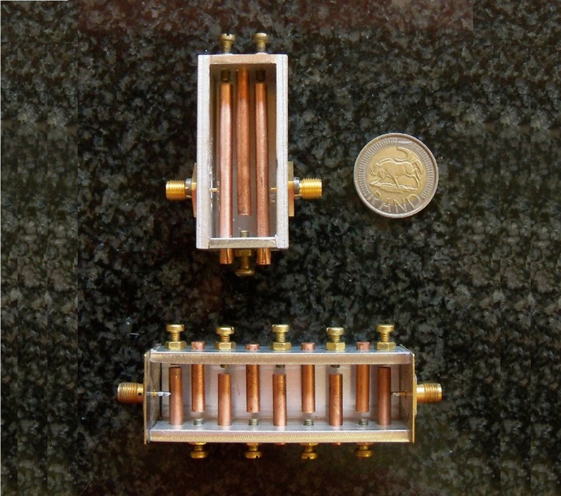
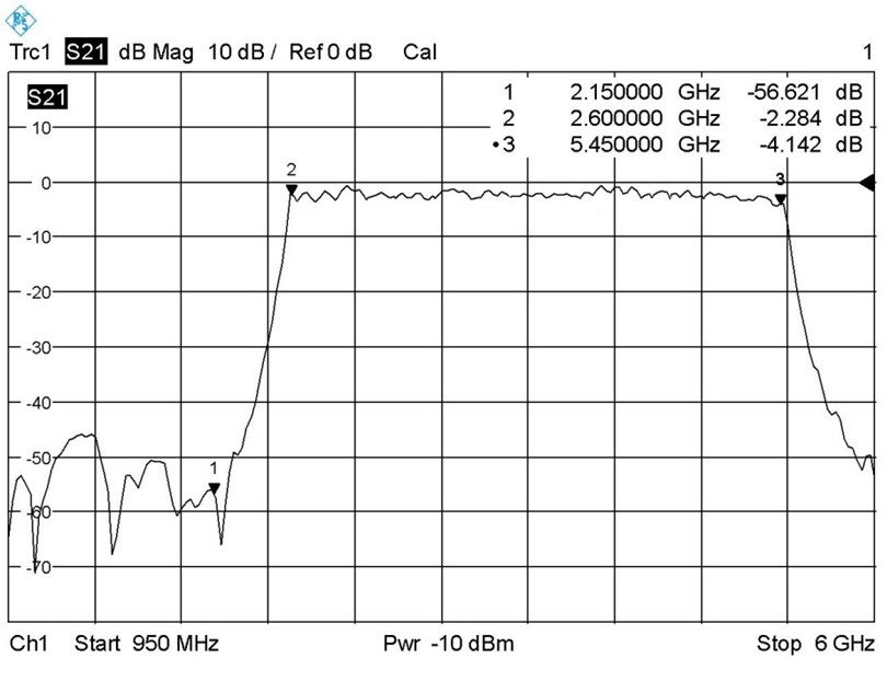
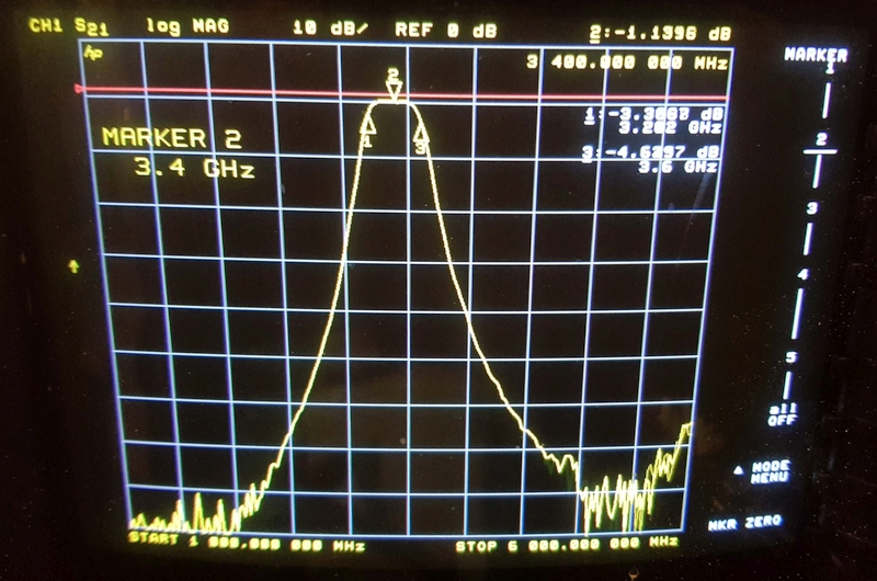
A second verification was done by my apprentice, who designed a 50 MHz Bandpass at 3 GHz. The report is attached below.
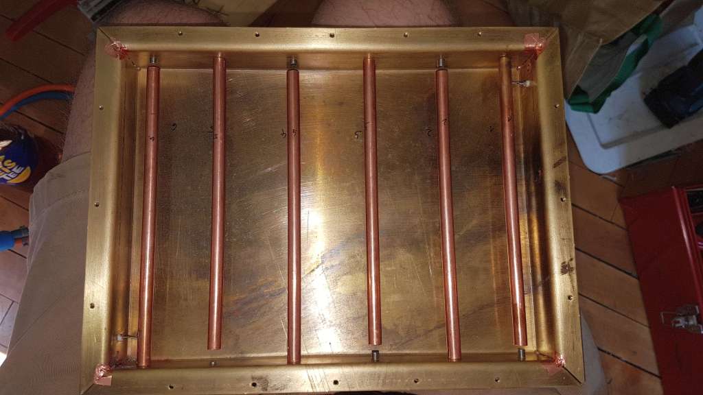
Andre (I assume from South Africa) sent the following pics :
A Mechanical BeautyElectronic Performance
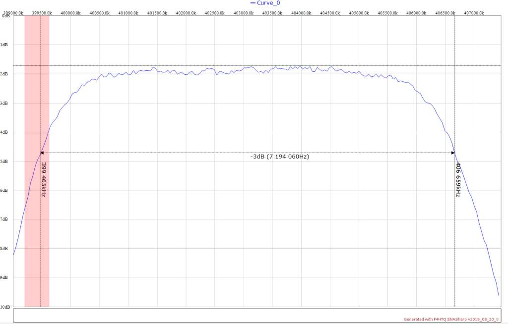
Lars (I assume from Norway) sent the following pics :
A Mechanical BeautyElectronic Performance
Philipp, OE8JPQ (I assume from Austria) sent the following pics :
A Mechanical BeautyElectronic Performance
THANK YOU ALL FOR THAT COLOURFUL FEEDBACK !!!
✈ Share your thoughts
The webmaster does not read these comments regularely. Urgent questions should be send via email.
Ads or links to completely uncorrelated things will be removed.
 ช้างเผือก