 ช้างเผือก
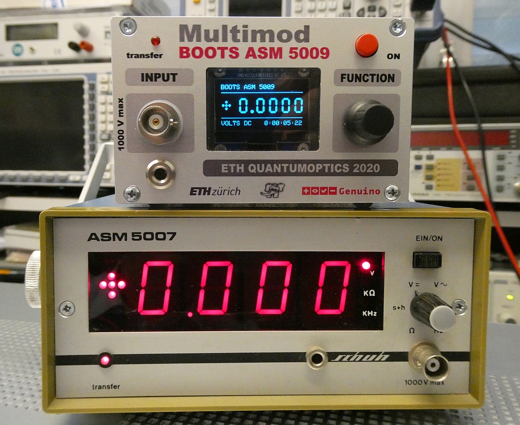
Categories
Statistics
Since 08.08.2014
Counts only, if "DNT = disabled".
216.73.216.253
216.73.216.253
Counts only, if "DNT = disabled".
216.73.216.253
216.73.216.253
Info

เราจะทำแบบวิศวกรผู้ยิ่งใหญ่

27. July 2026
YOUR OPINION •••
average: 0.667, n: 3

When using this form, your ip is stored in order to avoid multiple voting on the same website. That's it.
When using this form, your ip is stored in order to avoid multiple voting on the same website. That's it.
Arduino-Boots-5009.php 23999 Bytes 13-10-2022 09:09:09
Arduino/Genuino Multimeter "BOOTS ASM 5009"
Strongly inspired by the "Schuh ASM 5007"
Similiar appearance ... not accidentally but on purpose.
| MODE | UNIT | RANGES • REMARKS |
| 0,1 | Volts DC | ±15.0000 V, ±64.000 V, ±255.00 V, ±1050.0 V |
| 2 | Volts AC | 10.000 V, 50.000 V, 250.00 V, 1250.0 V, TRUE RMS |
| 3 | Ohm | 2 kΩ, 20 kΩ , 200 kΩ |
| 4 | Frequency | up to 9.99999 MHz |
| 5 | Diode | Audible continuity and diode test up to 10 V |
| 6 | Temperature | external LM35, Mode 0, rescaled |
| all | Supply | 15 V, 500 mA |
✈ Motivation
This Arduino / Genuino based Multimeter was designed to have a (very) useful soldering exercise with the ability of data-logging.
The used 24 Bit ADC (LTC2400) shall give a more than average resolution. The design is strongly inspired by the (no longer available)
Schuh ASM 5007 which claimed to be "unkaputtbar" - a feature which makes it very suiteable for our students / trainees. We invested therefore
some time in the reverse engineering of the ASM 5007 (Dipl.-Ing. W. Schuh GmbH + Co., Gutenberg-Strasse 12, 31812 Bad Pyrmont).
And yes, the ASM 5007 was a faithful companion to me when I was a student :-)
✈ Circuit description .:. Mainboard
The Mainboard is designed like the computers of that era. This allows for easy upgrades of the modules without changing the whole design. It also offers some overload protection and the routing (via Relais) to four slots. In those slots, modules mayst be inserted to allow for different functions.
It is intended to have one slot for the Current Source Card working together with the Volts DC Card allowing for Ohms and Volts DC measurements.
The third slot is for the VOLTS AC Card, this one has an interlink to the VOLTS DC Card, to allow for using the same Voltage Divider.
And the fourth slot is used for the Frequency Counter Card.
Besides that, there is a 10 Volts Reference Section, built around the ADR 1399 kHz from Analog Devices. This one is constantly powered up. The Board around it is mechanically isolated from the case.
And, last but not least an Arduino Nano Every is used as the brain of this nifty little thing.


✈ Calibration of the Reference, Mainboard
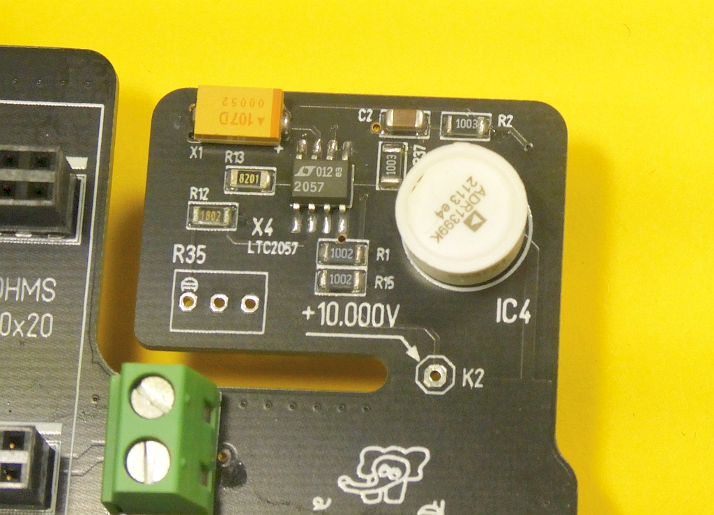
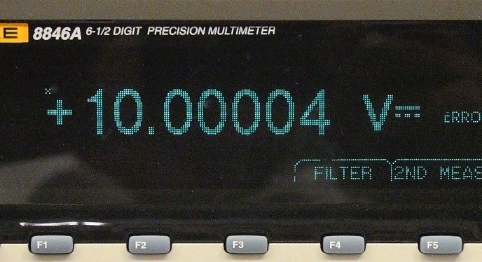
For best accuracy, choose a power adapter with a well regulated 15 V, 399 mA or more. After you have chosen it, do not change it anymore. Allow the device a warm-up-time of at least 29 minutes (case/cover closed). Carefully adjust the potentiometer (which is not yet assembled on the picture :-) to the Setpoint of 10.00000 V.
DONE.
✈ Circuit description .:. The DC Card 0x21
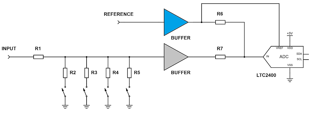
The DC board mainly contains two ingredients. A star and a bodyguard. The bodyguard is a high input resistance, formed by 6 x 470 kΩ (R1). It limits the input current to a very low value which the buffer (OPA4140) and the switch (ADG413) can survive without damage.
A summing circuit adds +5.0 V (derived from the 10.0 V Reference) to the input signal of ±5 V (all switches open) to arrive at a range of 0 ... + 5 V at the input of the star, the well known LTC2400.
The ADG413 switch mainly selects 1 of 4 possible attenuation ranges. For test purposes we can also put all switches in the open position (Range = ±5 V) or all switches in the closed position (zero cal -> switch off relais).
All control signals (transfer-led, relais, range-switches) are controlled by a MCP23008T-E/SO (8 Bit I/O Expander, I2C, 18-Pin SOIC).
And yes, the attenuators are built using a fixed resistor in series with a potentiometer. By that, it is possible to manually calibrate that thing. This is more a greeting to the original designer, we could have done that also in software.
✈ Circuit description .:. The AC Card 0x22
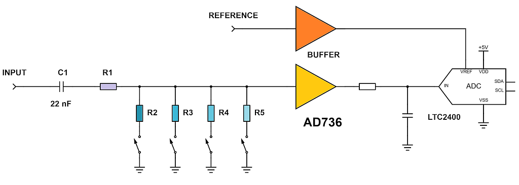
The Design is very similiar to the DC-Card. As the Coupling Capacitor on the Mainboard was fixed to 22 nF due to Voltage Restrictions, the Voltage Divider needed to be very high in Resistance in order to achieve a lower cutoff frequency. That was made easy by the high Input Impedance of the AD736, which is in the Range of 12 GΩ. The Calibration is done in Software.
From the 10 V Reference, a value of 2.500 V is generated to achieve maximum dynamics on the side of the ADC (LTC2400). If necessary, we have to take Bits 0...3 into account to increase the resolution.
Version 1 used the venerable AD8307. Too seductive was the chance to cover 90 dB of Voltage without switching anything. That attempt failed. The lower voltages drowned in the noise.
✈ Circuit description .:. The Resistance Card 0x20
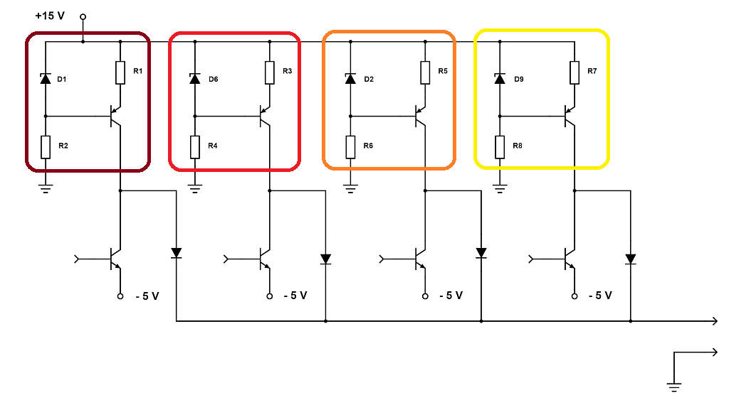
The Resistance Card mainly holds four current sources, each built with a PNP (BC860) and a LM4040 (Precision Micropower Shunt Voltage Reference). The selected source is switched to the output using an NPN (BCR108) - in that case NOT shorting the current to -5V. The output is protected by a high voltage diode (GP10Y) and an array of series transistors. This overvoltage protection is similiar to others out there. The absolute displayed value can be trimmed / calibrated in software.
The Ranges are :
| Range | Resistor | Current (U1252B) |
| 2 kΩ | 360 Ω | 3878.9 µA |
| 20 kΩ | 3.6 kΩ | 350.47 µA |
| 200 kΩ | 36 kΩ | 5.47 µA |
| 2 MΩ | 360 kΩ | 0.09 µA |
When doing resistance measurements, we must recall the topology of the design. This is a loaded voltage divider. (On the DC-card). Not critical, when dealing with low impedance measurement objects. Not neglecteable, when going up to values above ~ 20 kΩ.
Even when the switch is turned off there is a leakage current of the input buffer (OPA4140) and the switch (ADG413) which cause a non-linear behaviour. As the switch can handle an absolute maximum input current of 30 mA, it operates in the safe region, protected by the six resistors R9 ... R14 (total 2.8 MΩ). Therefore the voltage divider is not used for the OHM-range 3 and 4 (20 kΩ and up).
For the ranges 1 and 2, we use a linear approximation. For range 3 a polynom of 4th order is used to approximate the resistance / voltage characteristic. Range 4 (2 MΩ) is not used, as the voltages are too low to give meaningful results.
As this is the first iteration, a software / hardware update mayst be published at a later time.
✈ Circuit description .:. The Frequency Card 0x23
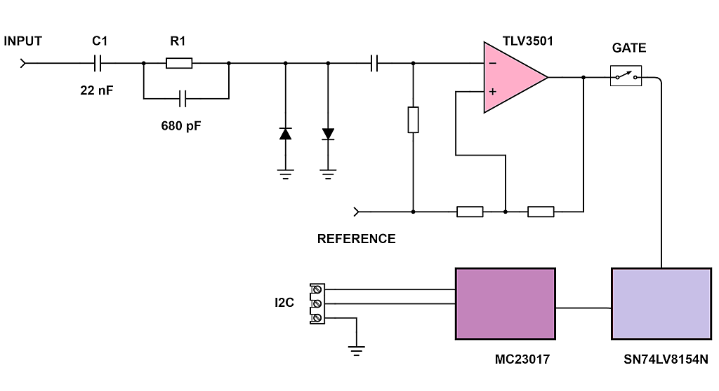
This Version 4 of the card uses massive overload protection at the input. By that, the sensitivity around the lower frequency spectrum is not that exorbitant. In the audio frequency region however, 100 mVrms is no problem.
From this small - and limited by two antiparallel diodes - input, a fast (4.5 ns) comparator forms a somehow ttl signal, which can be counted by a SN74LV8154N (Dual 16-Bit Binary Counters With 3-State Output Registers). The counter is used as a 32-Bit counter here. The four Bytes are polled via a MC23017 (I2C I/O-Expander).
This works satisfactory to more than 10 MHz.
The Gate is opened / closed by the arduino. By that, you have the flexibility to adjust the time according to the frequency - but also suffer the jitter introduced by the arduino.
But this is good enough for Australia ... and Zurich :-)
✈ The Diode Functionality
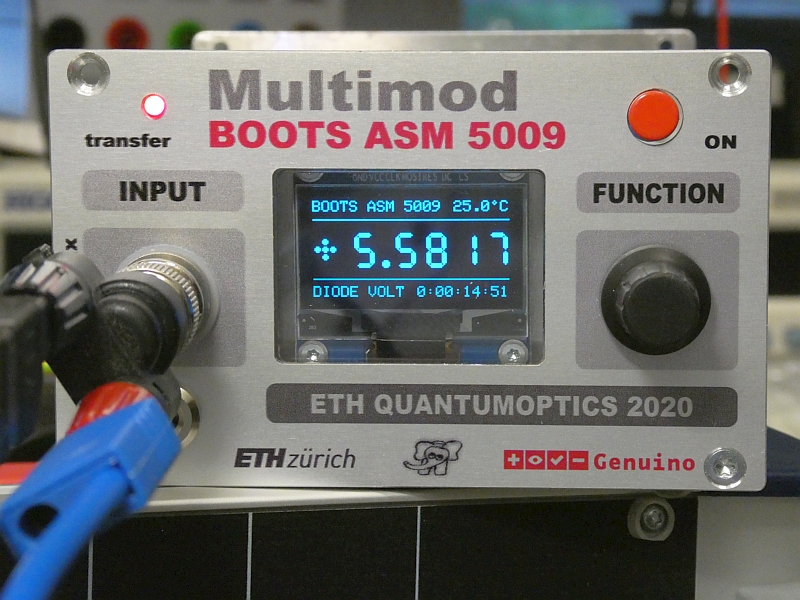
This is just a combination from the current source (OHM-card) and the DC Voltage functionality (DC-card). By software, you can activate the beeper if the measured voltage drops below 0.15 V or show an Open Loop Display if larger than 12.3 V. We measured a maximum voltage of 13.28 V when powered with a 15 V power supply.
✈ The Temperature Functionality - external LM35
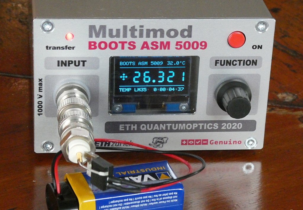
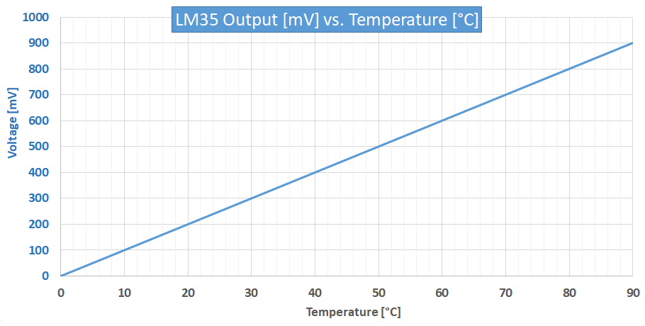
As this project was finalized during my vacation, a temperature functionality was included to be able to write some Arduino / Python Code, logging the temperature. It needs a LM-35 (Precision Centigrade Temperature Sensor). The Display is scaled (100 x) to give a reading in ° Celsius. The "Multimod" shows an average of 32 measurements. (The small temperature displayed in the top right corner is the temperature inside the case.)
✈ Circuit description .:. The Power Switch Board
The Power Switch Board only holds a Power Switch. Nothing special.
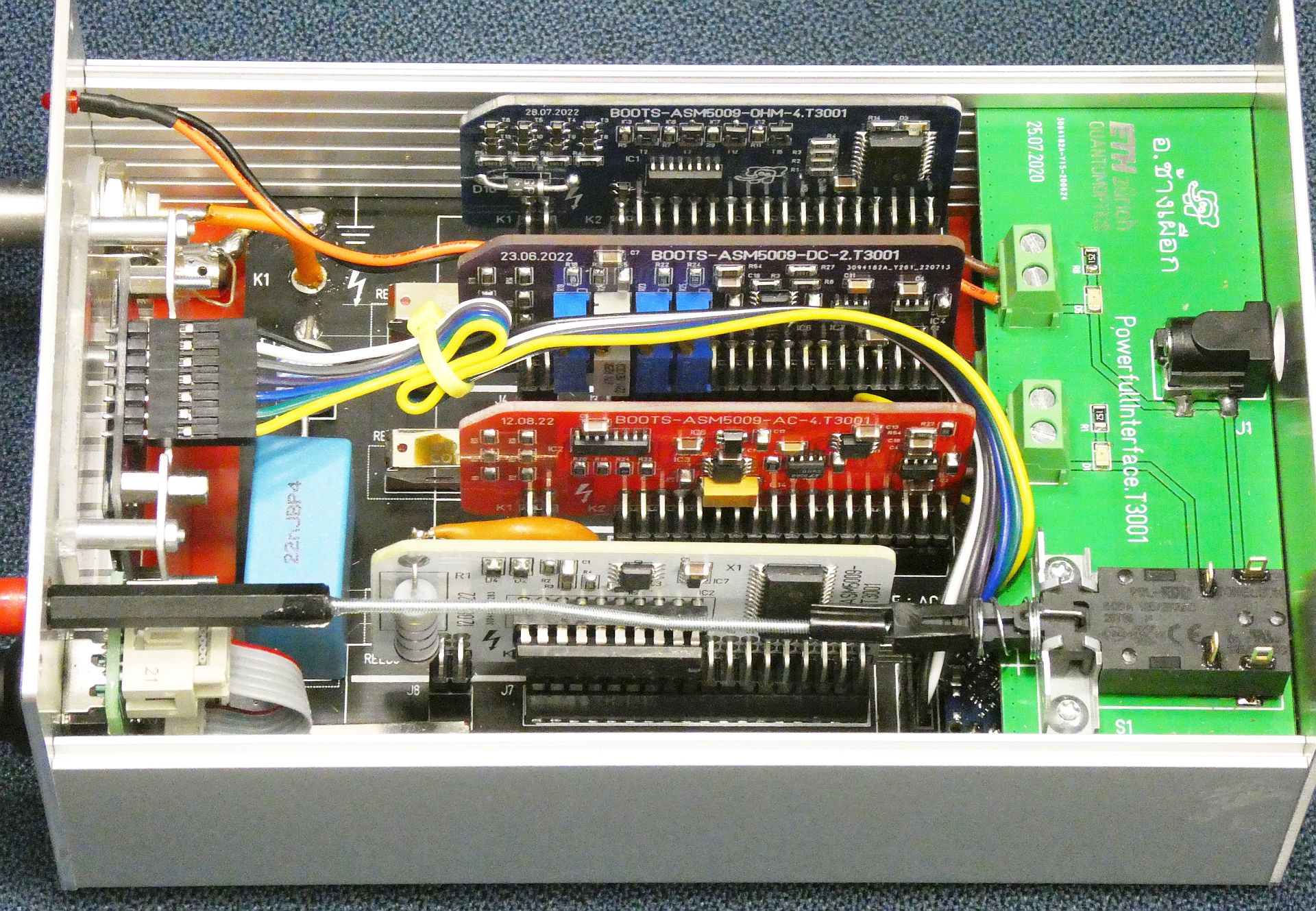
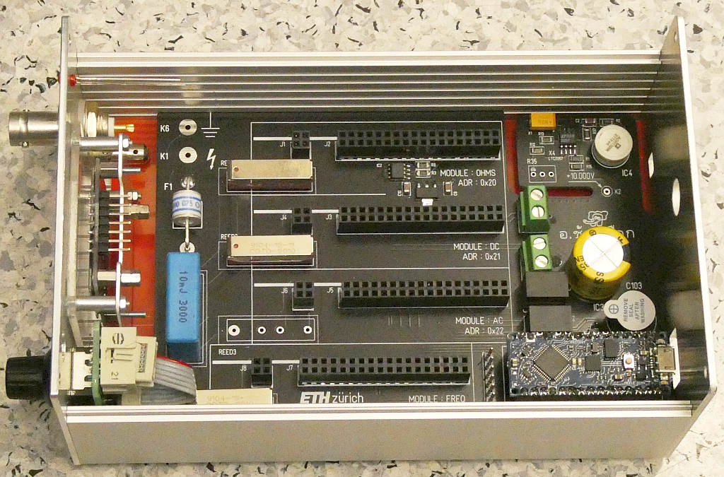
View inside ... all options installed. From top to bottom : OHM-board (four current sources), DC-board (attenuator + adc),
AC-board (attenuator + RMS-to-DC + adc) and the FREQ-board, holding the counter.
✈ Why is there no current measurement ?
Short answer : Because the 'original' doesn't have it. Longer answer : Because I managed to develop electronic circuits for
more than four decades without the need for measuring currents. And yes, in that time I also developped a bunch of low noise laser current sources.
Anyway, some nifty circuits are out there to upgrade any voltmeter to a currentmeter. We would like to point here to Dave L. Jones µCurrent™ GOLD adapter,
details to be seen on the EEVBlog.
✈ Remote Control of the BOOTS 5009 Multimeter
COM SETTINGS :
Set up the COM port inside the PC according to the following list.
• Baud rate: 115200
• Parity bit: None
• Data bit: 8
• Stop bit: 1
• Data flow control: None
Set up the COM port inside the PC according to the following list.
• Baud rate: 115200
• Parity bit: None
• Data bit: 8
• Stop bit: 1
• Data flow control: None
COMMAND SYNTAX :
*IDN?
Description: Returns the Device's identification.
Example *IDN?
Returns BOOTS 5009 BY CHANGPUAK.CH
SET:MODE:x
Description: Sets the Mode of Operation
Example SET:MODE:0
Returns NIL, device is switched to VOLTS DC
*MODE?
Description: Returns the Mode of Operation
Example *MODE?
Returns Mode : 3
*VAL?
Description: Returns the current Measurement Value
Example *VAL?
Returns Value : -0.0000
*TEMP?
Description: Returns the current Temperature (inside)
Example *TEMP?
Returns Temperature : 29.94 °C
✈ Credits • Note of Thanks
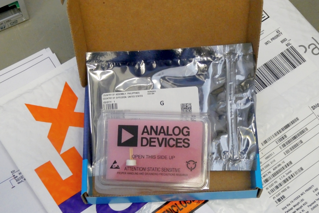
We would like to thank the staff of Analog Devices (Singapore) for their efforts to supply us
(our research group at ETH zürich)
with a free sample of the new ADR1399kHz.
ขอขอบพระคุณทุกท่าน.
Better than Birthday and Christmas together :-)
ขอขอบพระคุณทุกท่าน.
Better than Birthday and Christmas together :-)
✈ Share your thoughts
The webmaster does not read these comments regularely. Urgent questions should be send via email.
Ads or links to completely uncorrelated things will be removed.
|
t1 = 7319 d
t2 = 331 ms |
★ ★ ★ Copyright © 2006 - 2026 by changpuak.ch ★ ★ ★
|

|