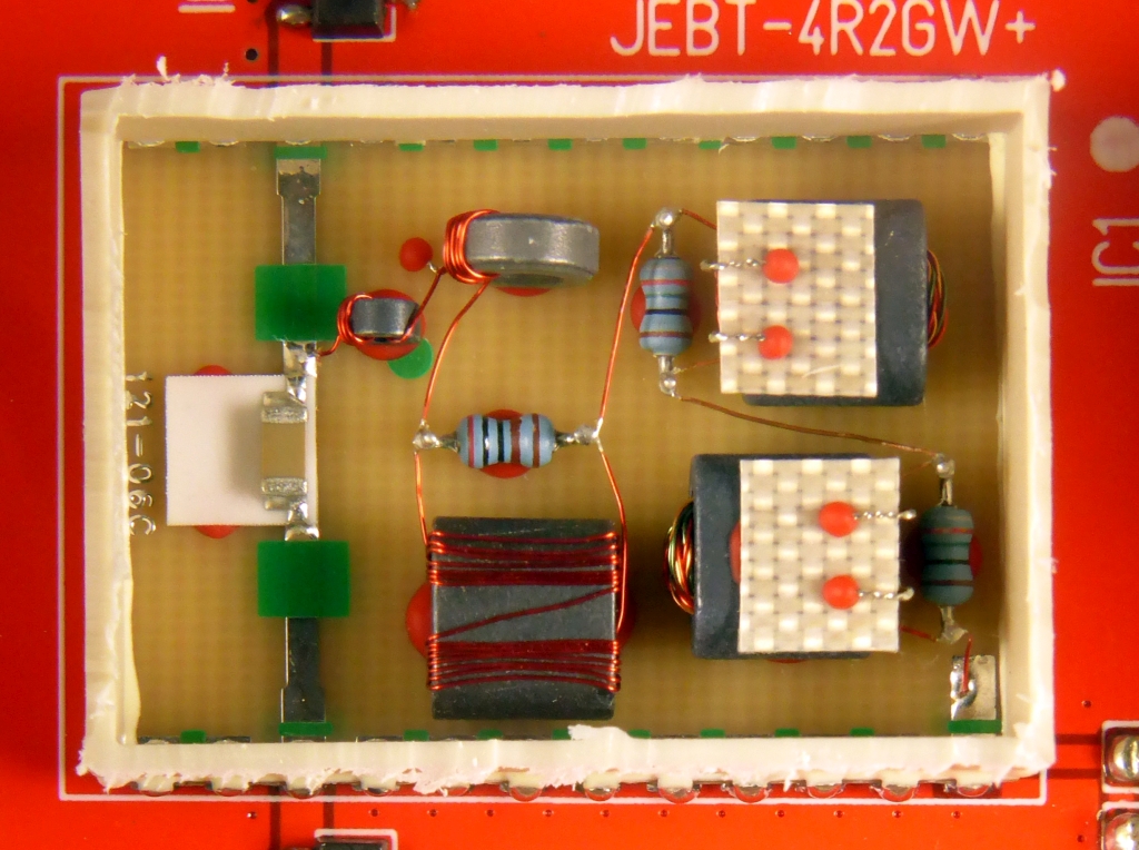
The JEBT-4R2GW+ from Mini Circuits covers 0.1 to 4200 MHz
✈ Application
Bias-Tees are used, whenever a source of DC power must be connected to an RF guiding cable.
The goal is, that the insertion shall not affect the RF power, transmitted through the same
cable. This method is used, when an LNA (which is mounted near the antenna) must be powered
via the antenna cable. It could also be used to combine a DC current with an RF carrier
in order to operate a laser diode.
In therory, the bias tee can be understood as an ideal capacitor that allows AC through but blocks
the DC bias and an ideal inductor that blocks AC but allows DC. In the real world so,
both of these components are not ideal, and for a broadband solution, more work needs to be
done to overcome parasitic effects.
As inductors with a core can get saturated - as the current gets too high - the inductivity
is reduced. With capacitors, the capacity mayst depend on the applied DC voltage.
This even makes the task more challenging.
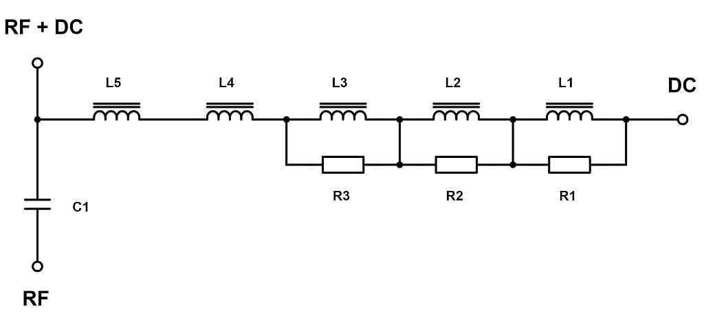
✈ Strategy
The schematic shows, that 5 inductors are used in series. Every one covers a certain frequency range,
so that the overall performance becomes very broadband.
You mayst assume, that the smaller ones (with respect to the picture on top of the page) are for the
upper end, whilst the big ones perform best at the lower cut-off.
The big ones are shorted with a resistor. This has the effect, that the Q is reduced in order
to increase the bandwidth.
✈ Simulation • Calculation
If you have Spice models / Measurement data of "your" inductors, you can use RFSim99 (e.g.)
to calculate the overall performance built on models.
If you are a fan of Murata, their Bias-T Inductor Selection Tool
works automatically and can deliver a really good starting point for your design.
✈ Specifications
Bandwidth • Frequency Response
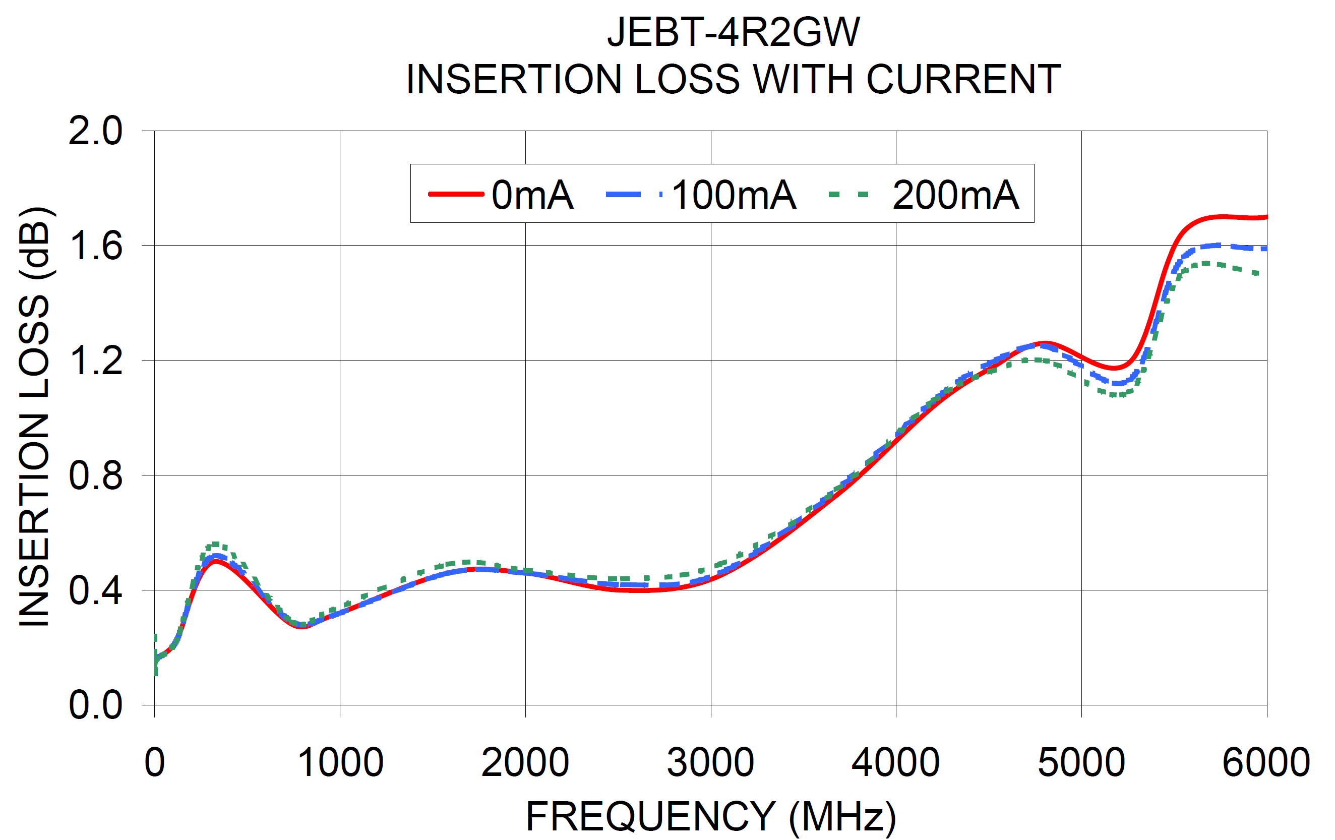
This ones are the obviously mandatory characteristics. The Bias-Tee should have a flat
Amplitude Response (S21) around the desired frequency of operation. It also shall have
a low insertion loss, as signals from an antenna are usually low and therfore precious.
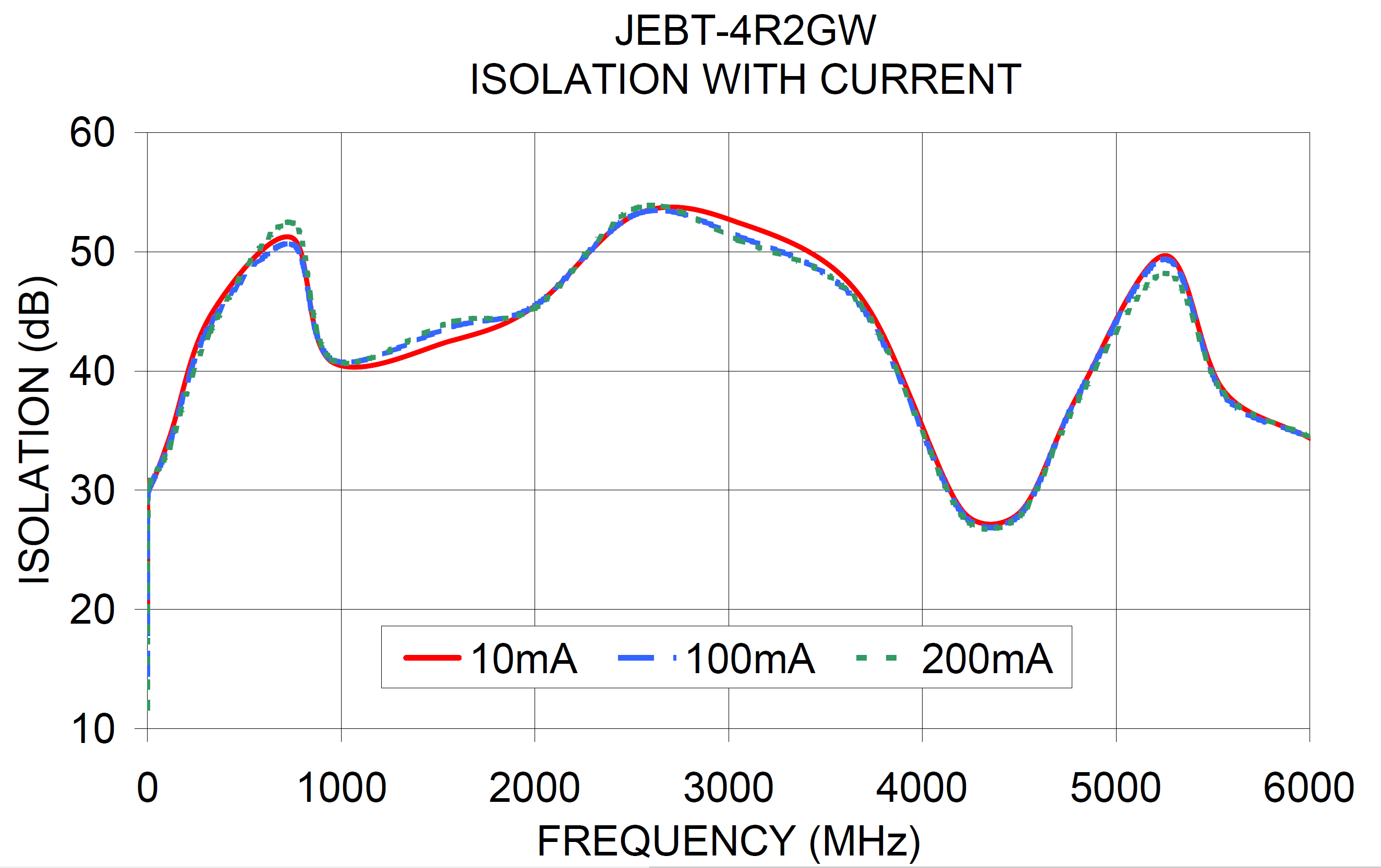
A low insertion loss between the RF and RF+DC port also means a high isolation between
the RF ports and the DC port. If you see, that the S21 is almost zero, you mayst guess,
that the S11 is very high !
Frequency Response of the JEBT-4R2GWIsolation of the JEBT-4R2GW
Both drawings are courtesy of Mini Circuits. You also see, that there are more curves,
depending on the current supplied through the DC port. As mentioned above, the incuctors
may saturate, i.e. the inductivity is limited / reduced when large currents are applied.
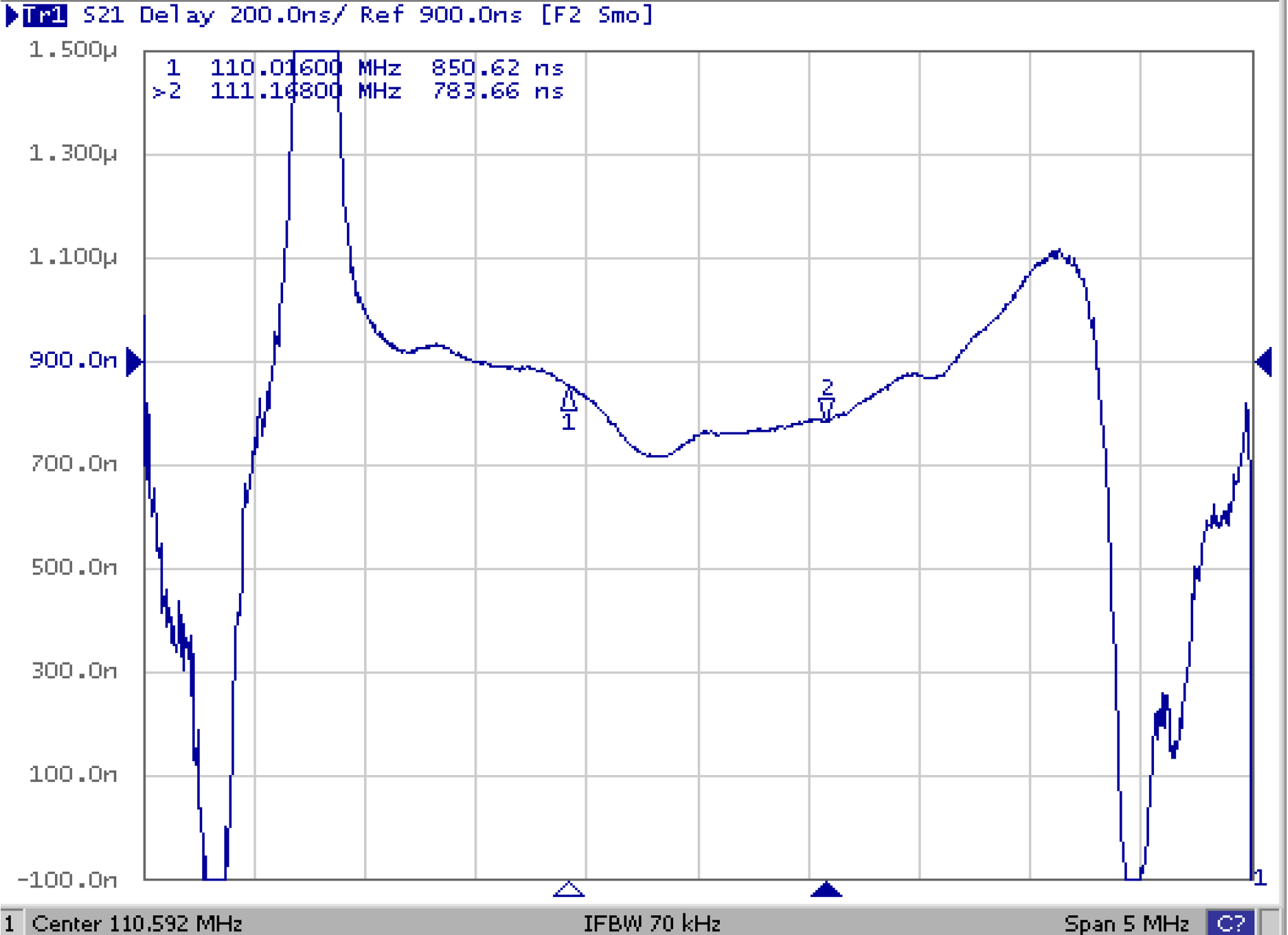
Linear Phase • Group Delay
Those two parameters are important, if you plan to transmit pulses or modulated RF carriers.
In case the phase of the Bias Tee is not linear, distortion will occur.
Source : [1] Datasheet of the SF1056B by MuRata, [2] "For signal distortion, phase matters" by EDN.
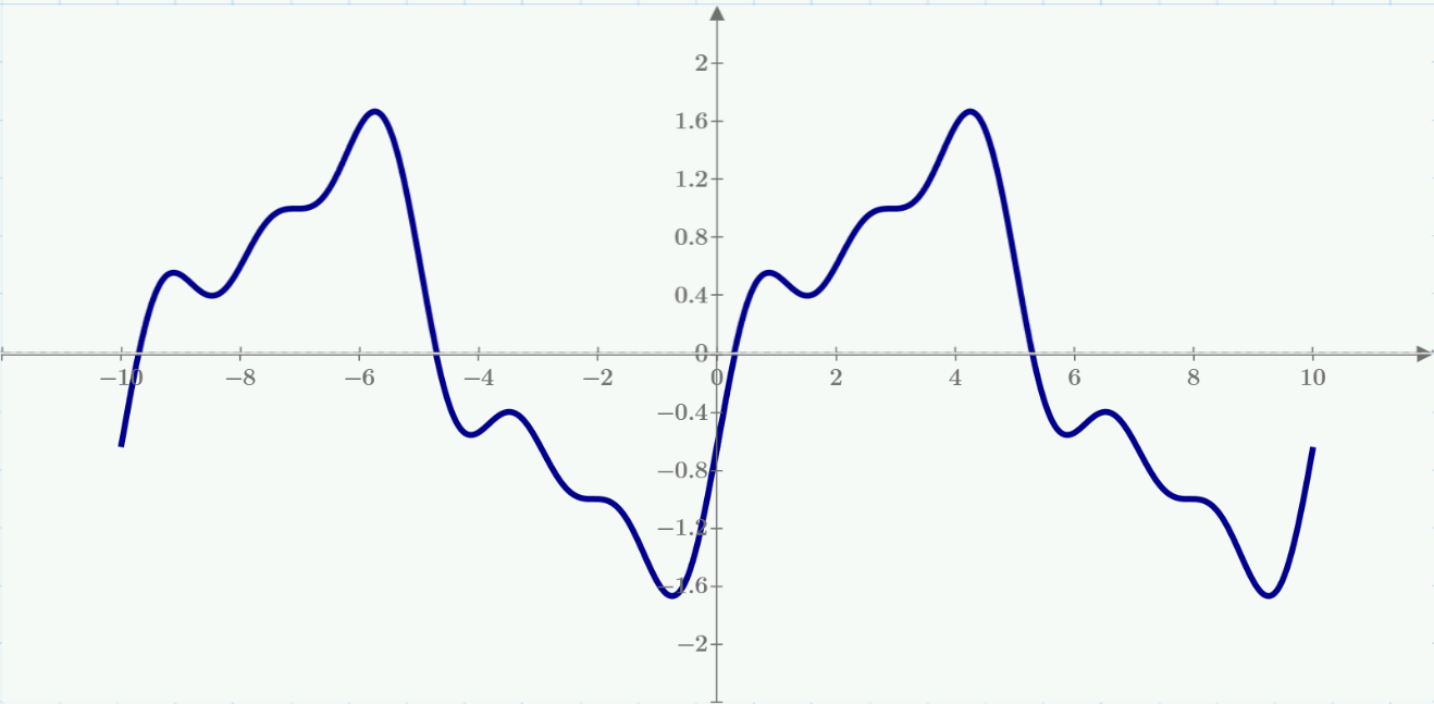
As the Nonlinearity of a Phase Response is not always easy to spot, Engineers invented the
Group Delay. The Group Delay is the derivative of the Phase Response.
✈ Share your thoughts
The webmaster does not read these comments regularely. Urgent questions should be send via email.
Ads or links to completely uncorrelated things will be removed.
 ช้างเผือก