 ช้างเผือก
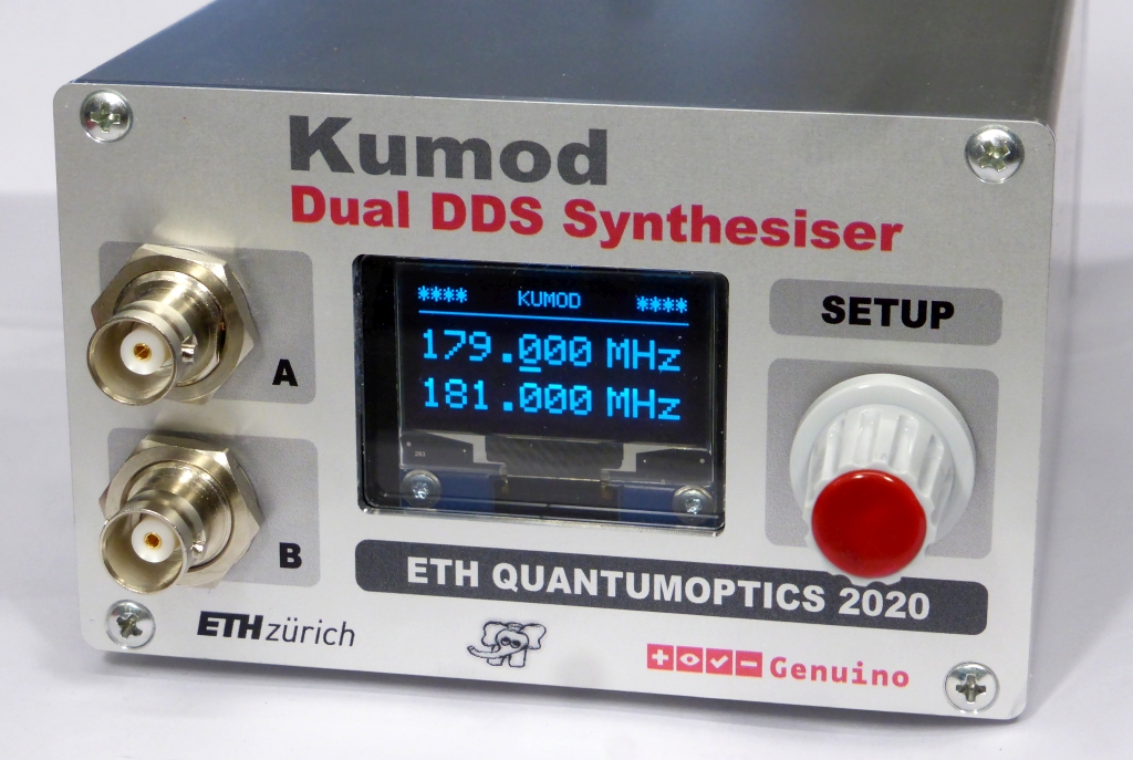
Categories
Statistics
Since 08.08.2014
Counts only, if "DNT = disabled".
216.73.216.253
216.73.216.253
Counts only, if "DNT = disabled".
216.73.216.253
216.73.216.253
Info

เราจะทำแบบวิศวกรผู้ยิ่งใหญ่

27. July 2026
YOUR OPINION •••
average: 0.001, n: 0

When using this form, your ip is stored in order to avoid multiple voting on the same website. That's it.
When using this form, your ip is stored in order to avoid multiple voting on the same website. That's it.
Arduino-Kumod.php 30363 Bytes 02-04-2021 19:55:09
Arduino/Genuino Kumod
A versatile Dual DDS Synthesiser with the AD 9958
The assembled prototype
✈ Motivation
As the Polarmod
worked nicely, we decided to create some kind of 'Spin-Off'. This Synthesiser can also be locked to a
10 MHz Reference, can be programmed via USB and offers many modes of operation.
It can serve as an I-Q-Source, a Two Tone generator, a Sweep Oscillator and can work in an IF-Offset Mode. A website on calculating IP3 can be found here.
"Ku" [in Thai : คู่ ] is the classificator for a 'pair' (e.g. a pair of boots, a couple, ...).
It can serve as an I-Q-Source, a Two Tone generator, a Sweep Oscillator and can work in an IF-Offset Mode. A website on calculating IP3 can be found here.
"Ku" [in Thai : คู่ ] is the classificator for a 'pair' (e.g. a pair of boots, a couple, ...).
✈ Block Diagam Kumod
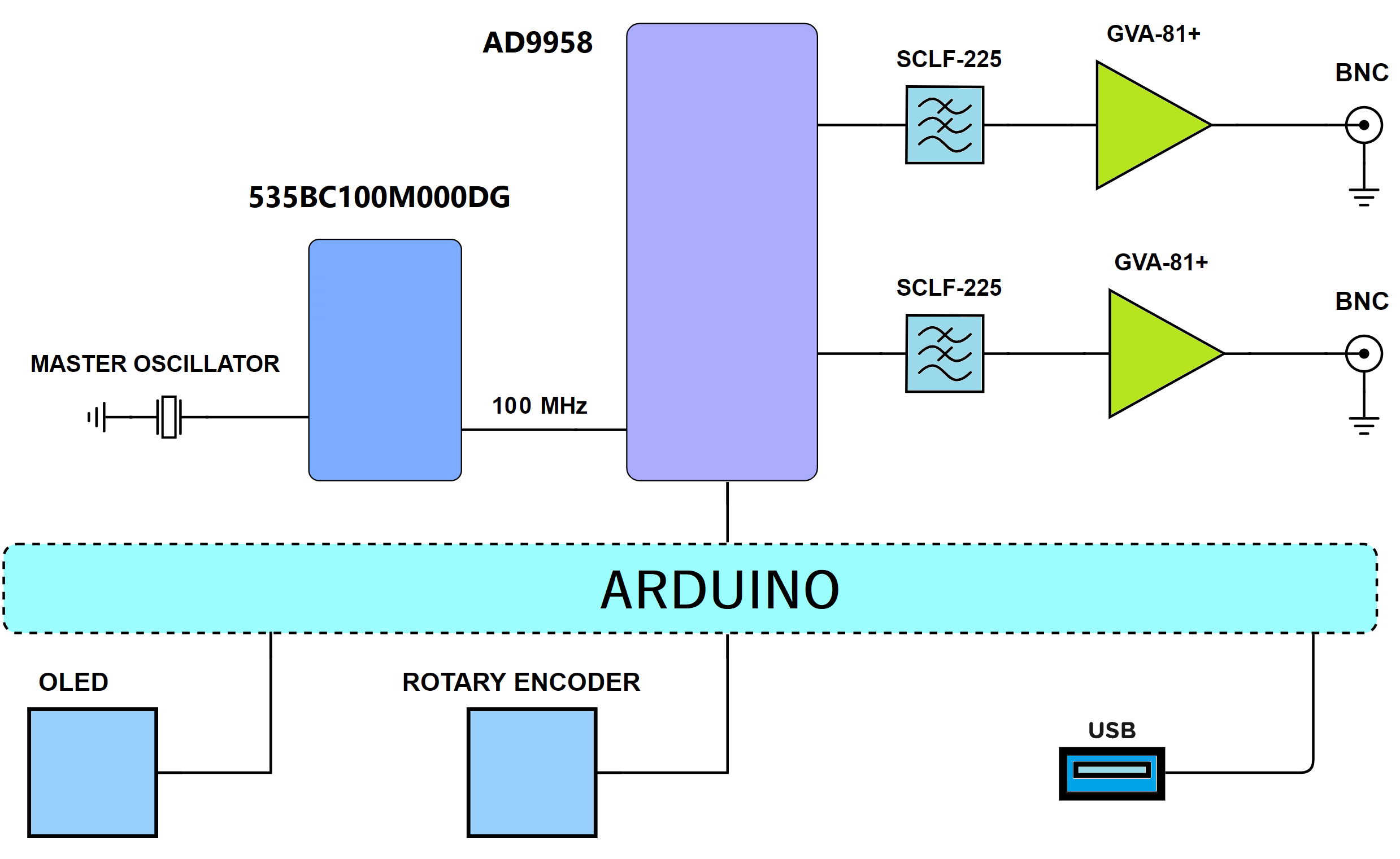
Block Diagram of the Kumod - a nifty little device
This device (Version 1, picture below) uses a free running XCO which is multiplied by a factor of 10 by the internal VCO/PLL of the AD9958. This allows for a Reference Clock of 500 MHz. Version 3 (see placement, below) can be populated with any 7 x 5 mm crystal oscillator or with our 100 MHz Ref Clock Module. Two internal Amplifier (GALI-51+, approx. 17 dB) boost the signal to + 10 dBm. In order to achieve a much lower cut-off (as when using the standard TCBT-14) we use two inductors in series, both damped with a resistor. Simulation (and measurement) show, that 1 MHz is by far not the end. The upper limit is somewhere in the region of 200 MHz, depending on your demands for image suppression. (An SCLF-190 lowpass-filter could be used here as well !)
Specifications :
| FREQUENCY RANGE | 1 MHz ... 200 MHz in 1 kHz steps (Software limited) |
| AMPLITUDE RANGE | - 20 ... + 10 dBm in 0.1 dB steps |
| PHASE RANGE | 0 ... 359.9° in 0.1° steps |
| REMOTE | USB (Arduino), not isolated |
| SUPPLY | + 7.5 V ... 9 V approx. 399 mA |
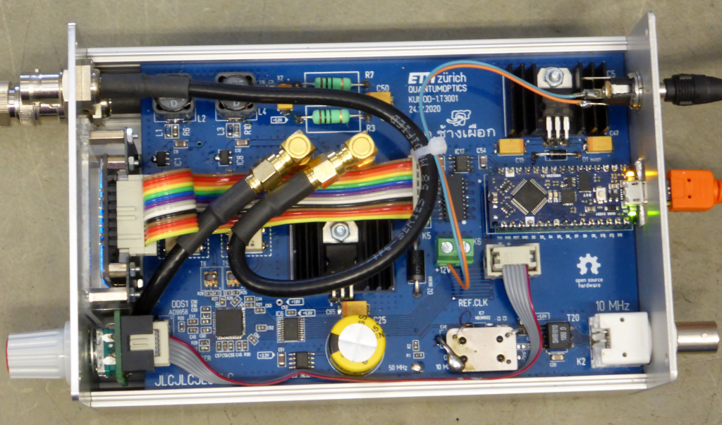
Inside View of Version 1 - with a 50 MHz XCO
✈ Amplitude Setting
The Amplitude can be controlled manually by writing the amplitude scale factor directly.
For this action to be successful, you need to set ACR[12] = 1 and ACR[11] = 0.
We measured the overall (inclusive GALI-51+ Amplifier) Setpoint (ASF) versus Power characteristics :
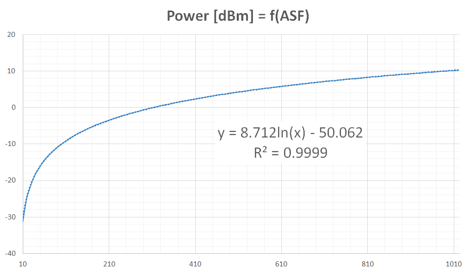
Our spreadsheet program was so kind to deliver a function which approximates the behaviour quite nicely. All which was left, was to solve for ASF (= Amplitude Scale Factor).
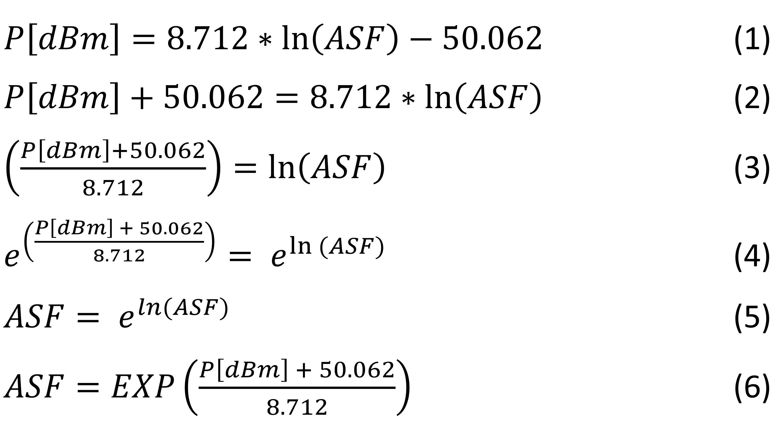
You'll find this in the code below, lines 242 and 255.
We measured the overall (inclusive GALI-51+ Amplifier) Setpoint (ASF) versus Power characteristics :
Our spreadsheet program was so kind to deliver a function which approximates the behaviour quite nicely. All which was left, was to solve for ASF (= Amplitude Scale Factor).
You'll find this in the code below, lines 242 and 255.
✈ Test Sketch for Arduino/Genuino Nano Every
Double click on code to select ...
/* //////////////////////////////////////////////////////////////////

  ARDUINO/Genuino Project "KUMOD", an DDS SYNTHESISER AD9958
  https://www.changpuak.ch/electronics/Arduino-Kumod.php
  Software Version 1.0 - 02.04.2021 by ALEXANDER SSE FRANK,
  on the auspicious occasion of
  HRH Princess Maha Chakri Sirindhorn's Birthday

  HELPFUL:
  randomnerdtutorials.com/guide-for-oled-display-with-arduino/

////////////////////////////////////////////////////////////////// */

#include <Wire.h>
#include <Adafruit_GFX.h>
#include <Adafruit_SH1106.h>


// DISPLAY
#define OLED_MOSI  A2
#define OLED_CLK   A3
#define OLED_DC    A0
#define OLED_CS    13
#define OLED_RESET A1

// ROTARY ENCODER
const int RotaryEncoder1 = A7 ;   // PRESSED
const int RotaryEncoder2 = 2 ;
const int RotaryEncoder3 = 3 ;
volatile boolean LEFT = false ;
volatile boolean RIGHT = false ;
volatile boolean READY = true ;
int PRESSCNT = 0 ;

// DDS VARIABLES
double FREQA = 100.0 ;
double FREQB = 120.0 ;
double PHASEA = 0.0 ;
double PHASEB = 199.0 ;
double AMPLA = 10.2 ;
double AMPLB = 10.2 ;
const double FREQ_MAX = 200.001 ;
const double FREQ_MIN = 0.999 ;
const double PHASE_MIN = 0.0 ;
const double PHASE_MAX = 359.9 ;
const double AMPL_MIN = -20.1 ;
const double AMPL_MAX = 10.1 ;
// {Fa, Fb, Aa, Ab, Pa, Pb} ;
int CPos[] = {4,4,3,3,3,3} ;
int MinCPos[] = {0,0,3,3,2,2} ;
int MaxCPos[] = {6,6,5,5,5,5} ;
int DotCPos[] = {3,3,4,4,4,4} ;
int MenuI = 0 ;
int MaxMenuI = 5 ;
const double REF = 500.000000 ;

Adafruit_SH1106 display(OLED_MOSI, OLED_CLK, OLED_DC, OLED_RESET, OLED_CS);

#if (SH1106_LCDHEIGHT != 64)
#error("Height incorrect, please fix Adafruit_SH1106.h!");
#endif


// /////////////////////////////////////////////////////////////
// Serial Communication Routines : EEPROM & DDS
// /////////////////////////////////////////////////////////////

#define EEPROM_24C01_I2CADDR 0x50

// Single-bit serial 2-wire mode
int DDS_RESET = 5 ;   // Active High Reset Pin
int DDS_SYNCIO = 6 ;
int DDS_SDIO2 = 7 ;
int DDS_SDIO1 = 8 ;
int DDS_SDAT = 9 ;
int DDS_SCLK = 10 ;
int DDS_CS = 11 ;
int DDS_IO_UPDATE = 12 ;


// ///////////////////////////////////////
void ResetDDS()
// ///////////////////////////////////////

{
  digitalWrite(DDS_RESET, HIGH) ;
  delay(9) ;
  digitalWrite(DDS_RESET, LOW) ;
  delay(9) ;
}


// //////////////////////////////////////////////////////////
void Energy()
// //////////////////////////////////////////////////////////

{
  digitalWrite(DDS_IO_UPDATE, HIGH) ;
  delay(1) ;
  digitalWrite(DDS_IO_UPDATE, LOW) ;
}


// //////////////////////////////////////////////////////////
void WriteDDS1(byte instruct,byte data)
// //////////////////////////////////////////////////////////

{
  digitalWrite(DDS_CS, LOW) ;
  shiftOut(DDS_SDAT, DDS_SCLK, MSBFIRST, instruct ) ;
  shiftOut(DDS_SDAT, DDS_SCLK, MSBFIRST, data) ;
  digitalWrite(DDS_CS, HIGH) ;
}


// //////////////////////////////////////////////////////////
void WriteDDS2(byte instruct,byte d1,byte d2)
// //////////////////////////////////////////////////////////

{
  digitalWrite(DDS_CS, LOW) ;
  shiftOut(DDS_SDAT, DDS_SCLK, MSBFIRST, instruct ) ;
  shiftOut(DDS_SDAT, DDS_SCLK, MSBFIRST, d1) ;
  shiftOut(DDS_SDAT, DDS_SCLK, MSBFIRST, d2) ;
  digitalWrite(DDS_CS, HIGH) ;
}


// //////////////////////////////////////////////////////////
void WriteDDS3(byte instruct,byte d1,byte d2,byte d3)
// //////////////////////////////////////////////////////////

{
  digitalWrite(DDS_CS, LOW) ;
  shiftOut(DDS_SDAT, DDS_SCLK, MSBFIRST, instruct ) ;
  shiftOut(DDS_SDAT, DDS_SCLK, MSBFIRST, d1) ;
  shiftOut(DDS_SDAT, DDS_SCLK, MSBFIRST, d2) ;
  shiftOut(DDS_SDAT, DDS_SCLK, MSBFIRST, d3) ;
  digitalWrite(DDS_CS, HIGH) ;
}


// //////////////////////////////////////////////////////////
void WriteDDS4(byte instruct,byte d1,byte d2,byte d3,byte d4)
// //////////////////////////////////////////////////////////

{
  digitalWrite(DDS_CS, LOW) ;
  shiftOut(DDS_SDAT, DDS_SCLK, MSBFIRST, instruct ) ;
  shiftOut(DDS_SDAT, DDS_SCLK, MSBFIRST, d1) ;
  shiftOut(DDS_SDAT, DDS_SCLK, MSBFIRST, d2) ;
  shiftOut(DDS_SDAT, DDS_SCLK, MSBFIRST, d3) ;
  shiftOut(DDS_SDAT, DDS_SCLK, MSBFIRST, d4) ;
  digitalWrite(DDS_CS, HIGH) ;
}


// //////////////////////////////////////////////////////////
void UpdateFTW()
// //////////////////////////////////////////////////////////

{
  // DATASHEET PAGE 18
  // fout = FTW * fs / 2^32
  // fs / 2^32 is constant. = 0.000000116415321826934814453125
  // 2^32 / fs is constant. = 8’589’934.592
  // ///////////////////////////////////////////////////////
  // CHANNEL 0
  // ///////////////////////////////////////////////////////
  unsigned long  FTW = (unsigned long)(FREQA * 8589934.592 ) ;
  int Byte1 = (0xFF000000 & FTW) >> 24 ;
  int Byte2 = (0x00FF0000 & FTW) >> 16 ;
  int Byte3 = (0x0000FF00 & FTW) >> 8 ;
  int Byte4 = (0x000000FF & FTW) ;
  WriteDDS1(0x00, 0x70) ;
  WriteDDS4(0x04, Byte1, Byte2, Byte3, Byte4) ;
  Energy() ;
  // ///////////////////////////////////////////////////////
  // CHANNEL 1
  // ///////////////////////////////////////////////////////
  FTW = (unsigned long)(FREQB * 8589934.592 ) ;
  Byte1 = (0xFF000000 & FTW) >> 24 ;
  Byte2 = (0x00FF0000 & FTW) >> 16 ;
  Byte3 = (0x0000FF00 & FTW) >> 8 ;
  Byte4 = (0x000000FF & FTW) ;
  WriteDDS1(0x00, 0xB0) ;
  WriteDDS4(0x04, Byte1, Byte2, Byte3, Byte4) ;
  Energy() ;
}


// //////////////////////////////////////////////////////////
void UpdatePTW()
// //////////////////////////////////////////////////////////

{
  // CHANNEL 0 : CSR = 0x70
  // CHANNEL 1 : CSR = 0xB0
  // DATASHEET PAGE 18
  // pout = POW * 360 / 2^14
  // POW = pout * 2^14 / 360
  // 360 / 2^14 is constant. = 0.02197265625
  // 2^14 / 360 is constant. = 16384 / 360 = 45.511111111
  // ///////////////////////////////////////////////////////
  // CHANNEL 0
  // ///////////////////////////////////////////////////////
  int POW = (int)( PHASEA * 45.51111111111111 ) ;
  int EMSB = (POW & 0x3F00) >> 8 ;
  int ELSB = (POW & 0x00FF) ;
  WriteDDS1(0x00, 0x70) ;
  WriteDDS2(0x05, EMSB, ELSB) ;
  Energy() ;
  // ///////////////////////////////////////////////////////
  // CHANNEL 1
  // ///////////////////////////////////////////////////////
  POW = (int)( PHASEB * 45.51111111111111 ) ;
  EMSB = (POW & 0x3F00) >> 8 ;
  ELSB = (POW & 0x00FF) ;
  WriteDDS1(0x00, 0xB0) ;
  WriteDDS2(0x05, EMSB, ELSB) ;
  Energy() ;
}


// //////////////////////////////////////////////////////////
void UpdateASF()
// //////////////////////////////////////////////////////////
// Manual mode allows the user to directly control the output
// amplitude by manually writing to the amplitude scale factor
// value in the ACR (Register 0x06). Manual mode is enabled
// by setting ACR[12] = 1 and ACR[11] = 0. Line 247, 261

{
  // CHANNEL 0 : CSR = 0x70
  // CHANNEL 1 : CSR = 0xB0
  // AMAX 2^10 - 1 = 1023 approx. 10.23 dBm
  // AMIN = 100 ;
  // ///////////////////////////////////////////////////////
  // CHANNEL 0
  // ///////////////////////////////////////////////////////
  unsigned int ASF = pow(2.71828182846, (( AMPLA + 50.062 )/8.712)) ;
  // Serial.print("ASF #A : ");
  // Serial.println(ASF,DEC);
  int ONE = 0x00 ;
  int TWO = (ASF & 0x000300) >> 8 ;
  TWO |= 0x14 ;
  int TRI = (ASF & 0x0000FF) ;
  WriteDDS1(0x00, 0x70) ;
  WriteDDS3(0x06, ONE, TWO, TRI) ;
  Energy() ;
  // ///////////////////////////////////////////////////////
  // CHANNEL 1
  // ///////////////////////////////////////////////////////
  ASF = pow(2.71828182846, (( AMPLB + 50.062 )/8.712)) ;
  // Serial.print("ASF #B : ");
  // Serial.println(ASF,DEC);
  // Serial.println("------------------");
  ONE = 0x00 ;
  TWO = (ASF & 0x000300) >> 8 ;
  TWO |= 0x14 ;
  TRI = (ASF & 0x0000FF) ;
  WriteDDS1(0x00, 0xB0) ;
  WriteDDS3(0x06, ONE, TWO, TRI) ;
  Energy() ;
}


// /////////////////////////////////////////////////////////////
// ANALOG INPUTS
// /////////////////////////////////////////////////////////////

double SUPPLY = 0.0 ;
int SUPPLY_ARD_PIN = A6 ;

void UpDateSupplyVoltage()
{
  SUPPLY = map(analogRead(SUPPLY_ARD_PIN),0,1023,0,2048)/100.0 ;
}


// /////////////////////////////////////////////////////////////
// SUBROUTINES DISPLAY.
// /////////////////////////////////////////////////////////////


void UpdateDisplay()
{
  display.clearDisplay();
  display.setTextSize(1);
  display.setTextColor(WHITE);
  display.setCursor(0,0); display.print("****");
  display.setCursor(48,0); display.print("KUMOD");
  display.setCursor(104,0); display.print("****");
  display.drawLine(0, 12, 128, 12, WHITE);
  // --------------------------------------------
  // FREQUENCY CHANNEL A + CHANNEL B
  // --------------------------------------------
  if((MenuI == 0) || (MenuI == 1))
  {
  display.setTextSize(2) ;
  display.setCursor(0, 21);
  if (FREQA < 100.000) display.print(" ");
  if (FREQA < 10.000) display.print(" ");
  display.print(FREQA,3);
  display.setCursor(90, 21); display.print("MHz");
  // --------------------------------------------
  display.setCursor(0, 45);
  if (FREQB < 100.000) display.print(" ");
  if (FREQB < 10.000) display.print(" ");
  display.print(FREQB,3);
  display.setCursor(90, 45); display.print("MHz");
  }
  // --------------------------------------------
  // AMPLITUDE CHANNEL A + CHANNEL B
  // --------------------------------------------
  if((MenuI == 2) || (MenuI == 3))
  {
  display.setTextSize(2) ;
  display.setCursor(0, 21);
  display.print(" ");
  if ((AMPLA < 9.99) && (AMPLA > -9.99)) display.print(" ");
  if (AMPLA == 0.000) display.print(" ");
  if (AMPLA > 0.000) display.print("+");
  display.print(AMPLA,1);
  display.setCursor(90, 21); display.print("dBm");
  // --------------------------------------------
  display.setCursor(0, 45);
  display.print(" ");
  if ((AMPLB < 9.99) && (AMPLB > -9.99)) display.print(" ");
  if (AMPLB == 0.000) display.print(" ");
  if (AMPLB > 0.000) display.print("+");
  display.print(AMPLB,1);
  display.setCursor(90, 45); display.print("dBm");
  }
  // --------------------------------------------
  // PHASE CHANNEL A + CHANNEL B
  // --------------------------------------------
  if((MenuI == 4) || (MenuI == 5))
  {
  display.setTextSize(2) ;
  display.setCursor(0, 21);
  display.print(" ");
  if (PHASEA < 100.000) display.print(" ");
  if (PHASEA < 10.000) display.print(" ");
  display.print(PHASEA,1);
  display.setCursor(90, 21); display.print("Deg");
  // --------------------------------------------
  display.setCursor(0, 45);
  display.print(" ");
  if (PHASEB < 100.000) display.print(" ");
  if (PHASEB < 10.000) display.print(" ");
  display.print(PHASEB,1);
  display.setCursor(90, 45); display.print("Deg");
  }
  // CURSOR VERTICAL
  if(MenuI == 0) display.setCursor(0, 25) ; // FREQ A
  if(MenuI == 1) display.setCursor(0, 49) ; // FREQ B
  if(MenuI == 2) display.setCursor(0, 25) ; // AMPL A
  if(MenuI == 3) display.setCursor(0, 49) ; // AMPL B
  if(MenuI == 4) display.setCursor(0, 25) ; // PHASE A
  if(MenuI == 5) display.setCursor(0, 49) ; // PHASE B
  // CURSOR HORIZONTAL
  if(CPos[MenuI] == 0) display.print("");
  if(CPos[MenuI] == 1) display.print(" ");
  if(CPos[MenuI] == 2) display.print("  ");
  if(CPos[MenuI] == 3) display.print("   ");
  if(CPos[MenuI] == 4) display.print("    ");
  if(CPos[MenuI] == 5) display.print("     ");
  if(CPos[MenuI] == 6) display.print("      ");
  display.print("_");
  display.display();
}

// /////////////////////////////////////////////////////////////
// S E T U P
// /////////////////////////////////////////////////////////////

void setup()
{
  Serial.begin(115200) ;

  Wire.begin() ;

  // INIT OLED
  display.begin(SH1106_SWITCHCAPVCC);

  // SHOW STARTUP SCREEN
  display.clearDisplay();
  display.setTextSize(1);
  display.setTextColor(WHITE);
  display.setCursor(0,0); display.print("****");
  display.setCursor(48,0); display.print("KUMOD");
  display.setCursor(104,0); display.print("****");
  display.drawLine(0, 12, 128, 12, WHITE);
  display.setTextSize(1);
  display.setCursor(0, 21);
  display.println("A DUAL DDS GENERATOR");
  display.setCursor(0, 33);
  display.println("WITH THE AD9958. ");
  display.setCursor(0, 45);
  display.println("(C) ETH QUANTUMOPTICS");
  display.setCursor(0, 57);
  display.println("BUILT 02.04.2021");
  display.display();

  delay(999) ;

  pinMode(RotaryEncoder1, INPUT_PULLUP);
  pinMode(RotaryEncoder2, INPUT_PULLUP);
  pinMode(RotaryEncoder3, INPUT_PULLUP);
  // YELLOW
  attachInterrupt(digitalPinToInterrupt(RotaryEncoder2),
  RotaryEncoderISR2, FALLING);
  // GREEN
  attachInterrupt(digitalPinToInterrupt(RotaryEncoder3),
  RotaryEncoderISR3, FALLING);

  delay(1999);


  pinMode(DDS_RESET, OUTPUT) ;
  pinMode(DDS_SYNCIO, OUTPUT) ;
  digitalWrite(DDS_SYNCIO, LOW) ;
  pinMode(DDS_SDIO2, INPUT) ;
  pinMode(DDS_SDIO1, INPUT) ;
  pinMode(DDS_SDAT, OUTPUT) ;
  pinMode(DDS_SCLK, OUTPUT) ;
  pinMode(DDS_CS, OUTPUT) ;
  digitalWrite(DDS_CS, HIGH) ;
  pinMode(DDS_IO_UPDATE, OUTPUT) ;
  digitalWrite(DDS_IO_UPDATE, LOW) ;


  // INIT DDS
  ResetDDS() ;

  // Channel Select Register (CSR) (0x00) = BOTH
  WriteDDS1(0x00, 0xF0) ;

  // Function Register 1 (FR1) (0x01)
  WriteDDS3(0x01, 0xA8, 0x00, 0x00) ;

  // Function Register 2 (FR2) (0x02)
  WriteDDS2(0x02, 0x00, 0x00) ;

  // Channel Function Register (CFR) (0x03)
  WriteDDS3(0x03, 0x00, 0x03, 0x00) ;

  // Channel Frequency Tuning Word (CFTW0) (0x04)
  UpdateFTW() ;

  // PHASE TUNING WORD (0x05) ... OMITTED

  // Amplitude Control Register (ACR) (0x06)
  // MANUAL CONTROL, PAGE 28
  WriteDDS3(0x06, 0x00, 0x17, 0xFF) ;

  Energy() ;

  UpdatePTW() ;

  // CHECK SUPPLY
  UpDateSupplyVoltage() ;
  Serial.print("Supply : ") ;
  Serial.print(SUPPLY,2);
  Serial.println(" Volts");
}


// /////////////////////////////////////////////////////////////
// M A I N L O O P
// /////////////////////////////////////////////////////////////

void loop()
{
  // KEY ROTATED ?
  // //////////////////////////////////
  if(LEFT)
  // //////////////////////////////////
  {
  switch (MenuI)
    {
    case 0:
    // FREQUENCY A -
    switch (CPos[0])
      {
      case 0:
      FREQA -= 100.0 ;
      if(FREQA < FREQ_MIN) FREQA += 100.0 ; // UNDO :-)
      break;  // ---------------
      case 1:
      FREQA -= 10.0 ;
      if(FREQA < FREQ_MIN) FREQA += 10.0 ;
      break;  // ---------------
      case 2:
      FREQA -= 1.0 ;
      if(FREQA < FREQ_MIN) FREQA += 1.0 ;
      break;  // ---------------
      case 4:
      FREQA -= 0.1 ;
      if(FREQA < FREQ_MIN) FREQA += 0.1 ;
      break;  // ---------------
      case 5:
      FREQA -= 0.01 ;
      if(FREQA < FREQ_MIN) FREQA += 0.01 ;
      break;  // ---------------
      case 6:
      FREQA -= 0.001 ;
      if(FREQA < FREQ_MIN) FREQA += 0.001 ;
      break;  // ---------------
      }
      break ;
    case 1:
    // FREQUENCY B -
    switch (CPos[1])
      {
      case 0:
      FREQB -= 100.0 ;
      if(FREQB < FREQ_MIN) FREQB += 100.0 ; // UNDO :-)
      break;  // ---------------
      case 1:
      FREQB -= 10.0 ;
      if(FREQB < FREQ_MIN) FREQB += 10.0 ;
      break;  // ---------------
      case 2:
      FREQB -= 1.0 ;
      if(FREQB < FREQ_MIN) FREQB += 1.0 ;
      break;  // ---------------
      case 4:
      FREQB -= 0.1 ;
      if(FREQB < FREQ_MIN) FREQB += 0.1 ;
      break;  // ---------------
      case 5:
      FREQB -= 0.01 ;
      if(FREQB < FREQ_MIN) FREQB += 0.01 ;
      break;  // ---------------
      case 6:
      FREQB -= 0.001 ;
      if(FREQB < FREQ_MIN) FREQB += 0.001 ;
      break;  // ---------------
      }
    break;
    // ----------------------------
    case 2:
    // AMPLITUDE A -
    switch (CPos[2])
      {
      case 3:
      AMPLA -= 1.0 ;
      if(AMPLA < AMPL_MIN) AMPLA += 1.0 ; // UNDO :-)
      break;  // ---------------
      case 5:
      AMPLA -= 0.1 ;
      if(AMPLA < AMPL_MIN) AMPLA += 0.1 ;
      break;  // ---------------
      }
    break;
    // ----------------------------
    case 3:
    // AMPLITUDE B -
    switch (CPos[3])
      {
      case 3:
      AMPLB -= 1.0 ;
      if(AMPLB < AMPL_MIN) AMPLB += 1.0 ; // UNDO :-)
      break;  // ---------------
      case 5:
      AMPLB -= 0.1 ;
      if(AMPLB < AMPL_MIN) AMPLB += 0.1 ;
      break;  // ---------------
      }
    break;
    // ----------------------------
    case 4:
    // PHASE A -

    break;
    // ----------------------------
    case 5:
    // PHASE B -

    break;
   }
   UpdateFTW() ;
   UpdatePTW() ;
   UpdateASF() ;
   READY = true ;
   LEFT = false ;
   RIGHT = false ;
  }
  // //////////////////////////////////
  if(RIGHT)
  // //////////////////////////////////
  {
  switch (MenuI)
    {
    case 0:
    // FREQUENCY A +
    switch (CPos[0])
      {
      case 0:
      FREQA += 100.0 ;
      if(FREQA > FREQ_MAX) FREQA -= 100.0 ; // UNDO :-)
      break;  // ---------------
      case 1:
      FREQA += 10.0 ;
      if(FREQA > FREQ_MAX) FREQA -= 10.0 ;
      break;  // ---------------
      case 2:
      FREQA += 1.0 ;
      if(FREQA > FREQ_MAX) FREQA -= 1.0 ;
      break;  // ---------------
      case 4:
      FREQA += 0.1 ;
      if(FREQA > FREQ_MAX) FREQA -= 0.1 ;
      break;  // ---------------
      case 5:
      FREQA += 0.01 ;
      if(FREQA > FREQ_MAX) FREQA -= 0.01 ;
      break;  // ---------------
      case 6:
      FREQA += 0.001 ;
      if(FREQA > FREQ_MAX) FREQA -= 0.001 ;
      break;  // ---------------
      }
      break ;
    case 1:
    // FREQUENCY B +
    switch (CPos[1])
      {
      case 0:
      FREQB += 100.0 ;
      if(FREQB > FREQ_MAX) FREQB -= 100.0 ; // UNDO :-)
      break;  // ---------------
      case 1:
      FREQB += 10.0 ;
      if(FREQB > FREQ_MAX) FREQB -= 10.0 ;
      break;  // ---------------
      case 2:
      FREQB += 1.0 ;
      if(FREQB > FREQ_MAX) FREQB -= 1.0 ;
      break;  // ---------------
      case 4:
      FREQB += 0.1 ;
      if(FREQB > FREQ_MAX) FREQB -= 0.1 ;
      break;  // ---------------
      case 5:
      FREQB += 0.01 ;
      if(FREQB > FREQ_MAX) FREQB -= 0.01 ;
      break;  // ---------------
      case 6:
      FREQB += 0.001 ;
      if(FREQB > FREQ_MAX) FREQB -= 0.001 ;
      break;  // ---------------
      }
    break;
    // ----------------------------
    case 2:
    // AMPLITUDE A +
    switch (CPos[2])
      {
      case 3:
      AMPLA += 1.0 ;
      if(AMPLA > AMPL_MAX) AMPLA -= 1.0 ; // UNDO :-)
      break;  // ---------------
      case 5:
      AMPLA += 0.1 ;
      if(AMPLA > AMPL_MAX) AMPLA -= 0.1 ;
      break;  // ---------------
      }
    break;
    // ----------------------------
    case 3:
    // AMPLITUDE B +
    switch (CPos[3])
      {
      case 3:
      AMPLB += 1.0 ;
      if(AMPLB > AMPL_MAX) AMPLB -= 1.0 ; // UNDO :-)
      break;  // ---------------
      case 5:
      AMPLB += 0.1 ;
      if(AMPLB > AMPL_MAX) AMPLB -= 0.1 ;
      break;  // ---------------
      }
    break;
    // ----------------------------
    case 4:
    // PHASE A +

    break;
    // ----------------------------
    case 5:
    // PHASE B +

    break;
   }
   UpdateFTW() ;
   UpdatePTW() ;
   UpdateASF() ;
   READY = true ;
   LEFT = false ;
   RIGHT = false ;
  }

  // //////////////////////////////////
  // KEY PRESSED ?
  // //////////////////////////////////
  if(digitalRead(RotaryEncoder1) == LOW) PRESSCNT += 1 ;

  UpdateDisplay() ; // 50 ms
  delay(149) ;

  // WAIT FOR KEY RELEASED
  if(digitalRead(RotaryEncoder1) == HIGH)
  {
    // THAT WAS A SHORT ONE : ADVANCE CURSOR
    if((PRESSCNT > 0) && (PRESSCNT < 3))
    {
    CPos[MenuI] += 1 ;
    if(CPos[MenuI] == DotCPos[MenuI]) CPos[MenuI] += 1 ;
    if(CPos[MenuI] > MaxCPos[MenuI]) CPos[MenuI] = MinCPos[MenuI];
    PRESSCNT = 0 ;
    }
    // THAT WAS A LONG ONE : CHANGE MENUE ITEM
    if(PRESSCNT > 3)
    {
    MenuI += 1 ;
    if(MenuI > MaxMenuI) MenuI = 0 ;
    PRESSCNT = 0 ;
    }
  }
}


// /////////////////////////////////////////////////////////////
// INTERRUPT SERVICE ROUTINES
// /////////////////////////////////////////////////////////////

void RotaryEncoderISR2()
{
  // YELLOW
  if(READY)
  {
  LEFT = false ;
  RIGHT = false ;
  byte autre = digitalRead(RotaryEncoder3) ;
  if (autre > 0) RIGHT = true ;
  if (autre < 1) LEFT = true ;
  }
}

void RotaryEncoderISR3()
{
  // GREEN
  if(READY)
  {
  LEFT = false ;
  RIGHT = false ;
  byte autre = digitalRead(RotaryEncoder2) ;
  if (autre > 0) LEFT = true ;
  if (autre < 1) RIGHT = true ;
  }
}


// /////////////////////////////////////////////////////////////
// END OF FILE.
// /////////////////////////////////////////////////////////////
✈ Downloads


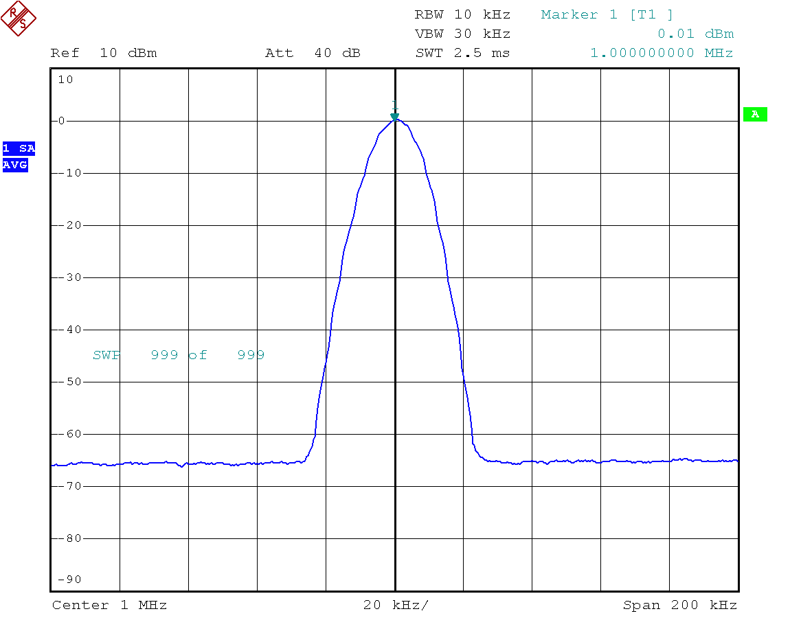
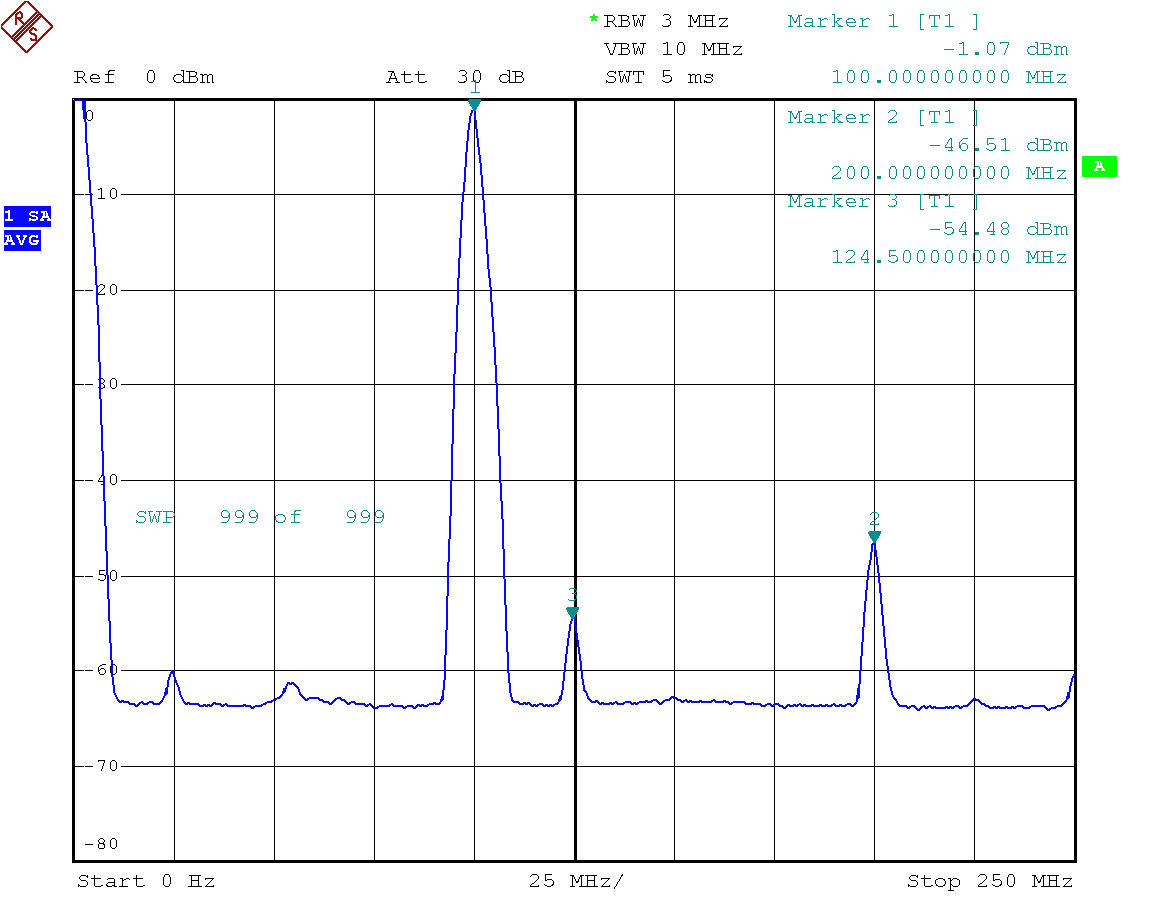
✈ Output Spectrum
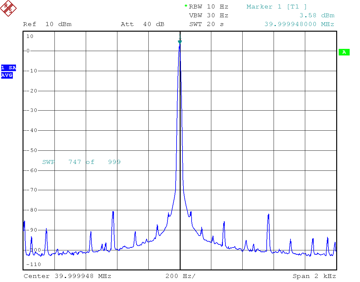
As with digital systems, there is a lot of spurious garbage visible.
Read more here.
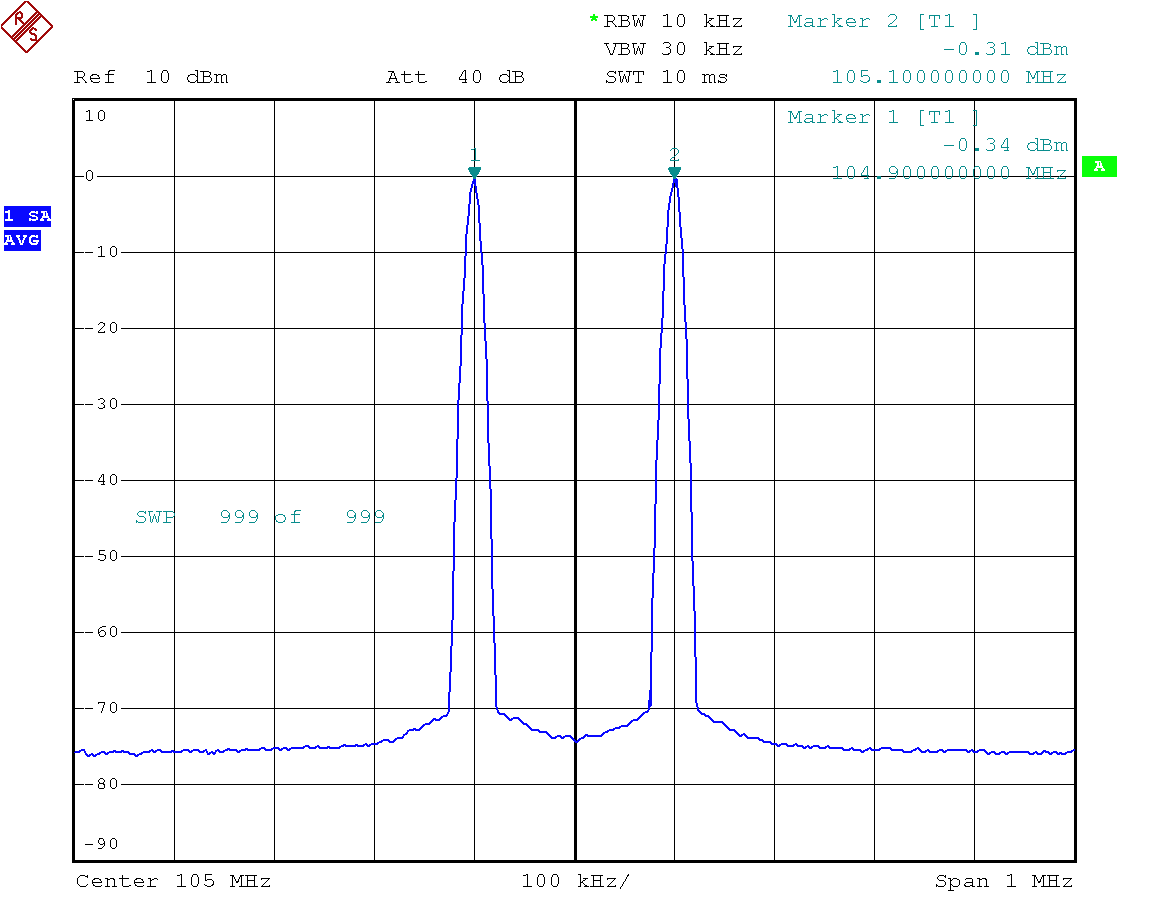
Output Spectrum, two tones added up with a ADP-2-1 from MiniCircuits.
Care must be taken, that no spurious signals are there, where the intermodulation products
are to be expected (when measuring IP3).
✈ Share your thoughts
The webmaster does not read these comments regularely. Urgent questions should be send via email.
Ads or links to completely uncorrelated things will be removed.
|
t1 = 7319 d
t2 = 398 ms |
★ ★ ★ Copyright © 2006 - 2026 by changpuak.ch ★ ★ ★
|

|