 ช้างเผือก
Categories
Statistics
Since 08.08.2014
Counts only, if "DNT = disabled".
216.73.216.203
216.73.216.203
Counts only, if "DNT = disabled".
216.73.216.203
216.73.216.203
Info




เราจะทำแบบวิศวกรผู้ยิ่งใหญ่
15. October 2026
YOUR OPINION •••
average: 2.000, n: 1

When using this form, your ip is stored in order to avoid multiple voting on the same website. That's it.
When using this form, your ip is stored in order to avoid multiple voting on the same website. That's it.
proj_06.php 5262 Bytes 04-03-2025 19:13:23
ELECTRONIC PROJECTS : ARTIFICIAL GROUND
Transform an Unipolar Power Supply into a Bipolar Power Supply
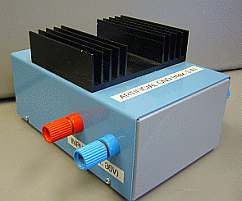
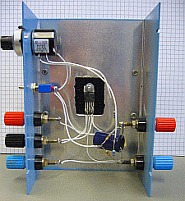
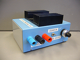
The Approach used here is just an active Voltage Divider. The GND of the Output
just has to be centered between the positive and the negative Supply. This can be
achieved using a Power Opamp such as the L149 (4A) or the L165 (3A) or any
equivalent type beeing available at your local hardware store. The Schematics
below shows how to wire it ...
3 Amp. Version using L165 from SGS Thomson.
C2 and C3 may be realised with 100µF // 100nF
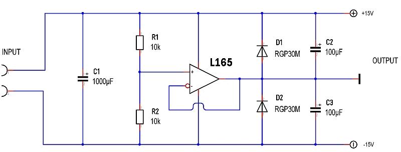
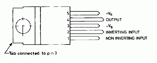
The Connections on the left side are considered to be the Inputs whilst the Connections on the right side form the Output. The Picture below shows the Pinout of the L165 Power Operational Amplifier from SGS Thomson. The Voltage Divider formed with R1 and R2 holds the positive Input of the OPAMP at half the Supply. As the OPAMP is connected as Voltage Follower or Impedance Converter, the Output (which is connected to the negative Input) will always try to reach the Voltage at the positive Input. It will remain exactly centered. (If you do not excruciate it to much :-)
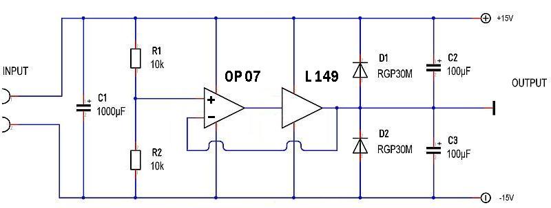
4 Amp. Version using L149 from SGS Thomson.
C2 and C3 may be realised with 100µF // 100nF
As this productuct is obsolete - check availability first !!! - or translate this knowledge to any other (newer and much better OPAMP)
When using the L149 the Schematics has to be expanded a little bit. One more OPAMP has to be added to achieve the desired function. The Schematics above shows how to wire it.
We thank Mr. Andrew Huber for his valuable Input and the Discussions about active Power Splits.
We thank Mr. Thomas Schaerer for pointing out, that the capacitors C2 and C3 greatly improve the high frequency behaviour. Also the ability for oscillation may increase if you choose the wrong Opamp. Read more here (in german languange).
3 Amp. Version using L165 from SGS Thomson.
C2 and C3 may be realised with 100µF // 100nF
The Connections on the left side are considered to be the Inputs whilst the Connections on the right side form the Output. The Picture below shows the Pinout of the L165 Power Operational Amplifier from SGS Thomson. The Voltage Divider formed with R1 and R2 holds the positive Input of the OPAMP at half the Supply. As the OPAMP is connected as Voltage Follower or Impedance Converter, the Output (which is connected to the negative Input) will always try to reach the Voltage at the positive Input. It will remain exactly centered. (If you do not excruciate it to much :-)
4 Amp. Version using L149 from SGS Thomson.
C2 and C3 may be realised with 100µF // 100nF
As this productuct is obsolete - check availability first !!! - or translate this knowledge to any other (newer and much better OPAMP)
When using the L149 the Schematics has to be expanded a little bit. One more OPAMP has to be added to achieve the desired function. The Schematics above shows how to wire it.
We thank Mr. Andrew Huber for his valuable Input and the Discussions about active Power Splits.
We thank Mr. Thomas Schaerer for pointing out, that the capacitors C2 and C3 greatly improve the high frequency behaviour. Also the ability for oscillation may increase if you choose the wrong Opamp. Read more here (in german languange).
✈ Share your thoughts
The webmaster does not read these comments regularely. Urgent questions should be send via email.
Ads or links to completely uncorrelated things will be removed.
|
t1 = 7399 d
t2 = 350 ms |
★ ★ ★ Copyright © 2006 - 2026 by changpuak.ch ★ ★ ★
|
|


