 ช้างเผือก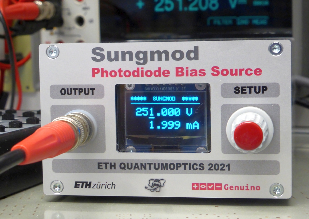
Categories
Statistics
Since 08.08.2014
Counts only, if "DNT = disabled".
216.73.216.203
216.73.216.203
Counts only, if "DNT = disabled".
216.73.216.203
216.73.216.203
Info




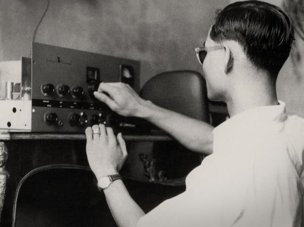
เราจะทำแบบวิศวกรผู้ยิ่งใหญ่
15. October 2026
YOUR OPINION •••
average: 0.001, n: 0

When using this form, your ip is stored in order to avoid multiple voting on the same website. That's it.
When using this form, your ip is stored in order to avoid multiple voting on the same website. That's it.
Arduino-Sungmod.php 15168 Bytes 29-09-2026 16:41:09
Arduino/Genuino "Sungmod"
A high Voltage Power Supply for Photodiodes
The prototype
 ระวัง ไฟฟ้า แรง สูง !
You have been warned ...
✈ Motivation
Some Photodiodes in our lab used for e.g. a Photon Counter need a High Voltage Bias.
This design uses two identical power transformers (connected back to back) to generate a
mains-isolated high voltage of approx. 300 V. This method was the preferred solution of my
(now retired) colleague, Mr. Paul Studerus. So consider this design somehow as a tribute
to yet another engineer with "Guru-Status", crossing my professional career.
✈ The Design
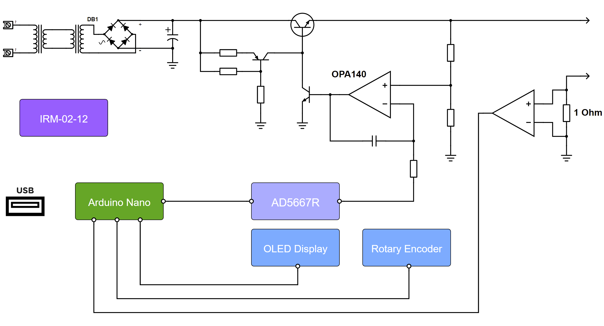
The Block Diagram of the "Sungmod"
The design is straightforward. As the dissipated power is very small, we used a linear regulator (IRF740/840).
The High Voltage (approx. 300V) is generated with two identical transformers, were the low voltage
side is connected back to back.
The Setpoint is generated by an AD5667R (Dual, 16-Bit nanoDACs® with 5 ppm/°C On-Chip Reference, I2C® Interface). A single Opamp (OPA140) controls the output voltage therefore, that it pulls the gate of the main transistor down. It is pulled up by a pnp transistor injecting approx. 1 mA into the gate.
The current is measured with a 1 Ω shunt. The voltage drop across it is amplified with a LT1789CS8-1 (Micropower, Single Supply Rail-to-Rail Output Instrumentation Amplifier) and then fed to an analog input of the Arduino. One could realise a current limit by that in software, but the prototype hasn't got that feature.
The Setpoint is generated by an AD5667R (Dual, 16-Bit nanoDACs® with 5 ppm/°C On-Chip Reference, I2C® Interface). A single Opamp (OPA140) controls the output voltage therefore, that it pulls the gate of the main transistor down. It is pulled up by a pnp transistor injecting approx. 1 mA into the gate.
The current is measured with a 1 Ω shunt. The voltage drop across it is amplified with a LT1789CS8-1 (Micropower, Single Supply Rail-to-Rail Output Instrumentation Amplifier) and then fed to an analog input of the Arduino. One could realise a current limit by that in software, but the prototype hasn't got that feature.
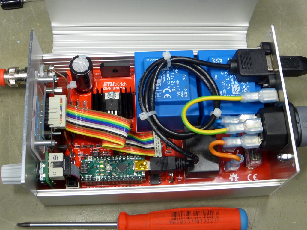
A look inside. And yes, the interesting components are below the ribbon cable :-)
✈ Downloads

✈ Test Sketch for Arduino/Genuino Nano
Double click on code to select ...
/* //////////////////////////////////////////////////////////////////

ARDUINO/Genuino Nano Sketch for Sungmod
https://www.changpuak.ch/electronics/Arduino-Sungmod.php
A High Voltage Power Supply for Photodiodes
Software Version 5.1
28.07.2019, Alexander Sse Frank
USEFUL:
learn.adafruit.com/adafruit-gfx-graphics-library/graphics-primitives

////////////////////////////////////////////////////////////////// */

#include <Adafruit_GFX.h>
#include <Adafruit_SH1106.h>
#include <Wire.h>

// DISPLAY

#define OLED_MOSI  11
#define OLED_CLK   12
#define OLED_DC    9
#define OLED_CS    8
#define OLED_RESET 10


Adafruit_SH1106 display(OLED_MOSI,OLED_CLK,OLED_DC,OLED_RESET,OLED_CS);

#if (SH1106_LCDHEIGHT != 64)
#error("Height incorrect, please fix Adafruit_SH1106.h!");
#endif

// ROTARY ENCODER

const int RotaryEncoder1 = 4 ;   // PRESSED
const int RotaryEncoder2 = 2 ;
const int RotaryEncoder3 = 3 ;

volatile bool LEFT = false ;
volatile bool RIGHT = false ;
volatile bool READY = true ;

// /////////////////////////////////////////////////////////////////////
// SUBROUTINES DAC AD5667R
// /////////////////////////////////////////////////////////////////////

// Pin 6 = ADDR is on GND >>> A0 = 1, A1 = 1
// Only VOUTA is used

const byte DAC_ADR = 0x0F ;
const float VoltFactor = 206.221 ;
const float MaxVolt = 270.000 ;
const float MinVolt = 0.000 ;
float SetVolt = 259.0 ;

void WriteDAC(byte cmd, unsigned int payload)
{
byte lsb = payload & 0xFF ;
byte msb = (payload & 0xFF00) >> 8 ;
Wire.beginTransmission(DAC_ADR) ;
Wire.write(cmd) ;
Wire.write(msb);
Wire.write(lsb);
Wire.endTransmission();
}

void UpdateVolt()
{
unsigned int Setpoint = 0x0000 ;
Setpoint = (int)(SetVolt * VoltFactor) ;
WriteDAC(0x10, Setpoint) ;
Serial.println(Setpoint,DEC) ;
}


// /////////////////////////////////////////////////////////////////////
// D I S P L A Y
// /////////////////////////////////////////////////////////////////////

float Current = 0.0 ;
const int CurrentPin = A6 ;
int CursorPos = 2 ;
int CurrBuff[32] ;      // STORES RAW VALUE
int CurrBuffPoint = 0 ;
const int MaxCurrBuffPoint = 31 ;
const float CurrentMuly = 5.0 / 1023.0 ;


void ReadCurrent()
{
int CurrBuffSum = 0 ;

CurrBuffPoint += 1 ;
if(CurrBuffPoint > MaxCurrBuffPoint) CurrBuffPoint = 0 ;
CurrBuff[CurrBuffPoint] = analogRead(CurrentPin) ;
CurrBuffSum = 0 ;
for(int i = 0 ; i < MaxCurrBuffPoint; i++)
{
CurrBuffSum += CurrBuff[i] ;
}
Current = CurrentMuly * (float)CurrBuffSum / MaxCurrBuffPoint ;
Serial.println(Current,3);
}


void UpdateDisplay()
{
ReadCurrent() ;
display.clearDisplay() ;
display.setTextSize(1) ;
display.setTextColor(WHITE) ;
display.setCursor(0,0); display.print("*****  SUNGMOD  *****") ;
display.drawLine(0, 12, 128, 12, WHITE) ;

display.setTextSize(2) ;
// VOLTAGE
display.setCursor(10, 21);
if (SetVolt < 99.999) display.print(" ");
if (SetVolt < 9.999) display.print(" ");
display.print(SetVolt,3);
display.setCursor(104, 21);
display.print("V");
// CURSOR
display.setCursor(10, 26);
if(CursorPos == 1) display.print(" ");
if(CursorPos == 2) display.print("  ");
if(CursorPos == 3) display.print("    ");
if(CursorPos == 4) display.print("     ");
if(CursorPos == 5) display.print("      ");
display.print("_");
// CURRENT
display.setCursor(10, 45);
if(Current < 99.999) display.print(" ") ;
if(Current < 9.9999) display.print(" ") ;
display.print(Current,3);
display.setCursor(104, 45);
display.print("mA");

display.display() ;
}


// /////////////////////////////////////////////////////////////////////
// S E T U P
// /////////////////////////////////////////////////////////////////////


void setup()
{
Serial.begin(115200);

Wire.begin() ;

pinMode(RotaryEncoder1, INPUT_PULLUP) ;
pinMode(RotaryEncoder2, INPUT_PULLUP) ;
pinMode(RotaryEncoder3, INPUT_PULLUP) ;

// YELLOW
attachInterrupt(digitalPinToInterrupt(RotaryEncoder2),
RotaryEncoderISR2, FALLING) ;
// GREEN
attachInterrupt(digitalPinToInterrupt(RotaryEncoder3),
RotaryEncoderISR3, FALLING) ;

// INIT OLED
display.begin(SH1106_SWITCHCAPVCC) ;

// SHOW STARTUP SCREEN
display.clearDisplay() ;
display.setTextSize(1) ;
display.setTextColor(WHITE) ;
display.setCursor(0,0);
display.println("*****  SUNGMOD  *****") ;
display.drawLine(0, 12, 128, 12, WHITE) ;
display.setTextSize(1) ;
display.setCursor(0,21) ;
display.println("A HIGH VOLTAGE") ;
display.setCursor(0,33) ;
display.println("POWER SUPPLY FOR") ;
display.setCursor(0,45) ;
display.println("PHOTODIODES.") ;
display.setCursor(0,57) ;
display.println("BUILT 23.10.2021") ;
display.display() ;


// DAC AD5667R
// RESET ALL
WriteDAC(0x28, 0x0001) ;
// POWER UP CHANNEL A
WriteDAC(0x20, 0x0001) ;
// SETUP LDAC PIN = BOTH DISABLED
WriteDAC(0x30, 0x0003) ;
// SWITCH ON REFERENCE
WriteDAC(0x38, 0x0001) ;

delay(999) ;

UpdateVolt() ;
UpdateDisplay() ;
}


// /////////////////////////////////////////////////////////////////////
// M A I N
// /////////////////////////////////////////////////////////////////////

void loop()
{
// KEY ROTATED ?
// //////////////////////////////////
if(LEFT)
// //////////////////////////////////
{
switch (CursorPos)
{
  case 0 :
	if((SetVolt - 100.0) >= MinVolt) SetVolt-=100.0 ;
	break ;
  case 1 :
	if((SetVolt - 10.0) >= MinVolt) SetVolt-=10.0 ;
	break ;
  case 2 :
	if((SetVolt - 1.0) >= MinVolt) SetVolt-=1.0 ;
	break ;
  case 3 :
	if((SetVolt - 0.1) >= MinVolt) SetVolt-=0.1 ;
	break ;
}
UpdateVolt() ;
delay(59) ;
READY = true ;
LEFT = false ;
RIGHT = false ;
}


// //////////////////////////////////
if(RIGHT)
// //////////////////////////////////
{
switch (CursorPos)
{
  case 0 :
	if((SetVolt + 100.0) <= MaxVolt) SetVolt+=100.0 ;
	break ;
  case 1 :
	if((SetVolt + 10.0) <= MaxVolt) SetVolt+=10.0 ;
	break ;
  case 2 :
	if((SetVolt + 1.0) <= MaxVolt) SetVolt+=1.0 ;
	break ;
  case 3 :
	if((SetVolt + 0.1) <= MaxVolt) SetVolt+=0.1 ;
	break ;
}
UpdateVolt() ;
delay(59) ;
READY = true ;
LEFT = false ;
RIGHT = false ;
}


// //////////////////////////////////
// KEY PRESSED ?
// //////////////////////////////////
if(!digitalRead(RotaryEncoder1))
{
CursorPos += 1 ;
if(CursorPos > 5) CursorPos = 0 ;
delay(199) ;
}


UpdateDisplay() ;
delay(59) ;


}


// /////////////////////////////////////////////////////////////////////
// INTERRUPT SERVICE ROUTINES
// /////////////////////////////////////////////////////////////////////

void RotaryEncoderISR2()
{
// YELLOW
if(READY)
{
LEFT = false ;
RIGHT = false ;
byte autre = digitalRead(RotaryEncoder3) ;
if (autre > 0) RIGHT = true ;
if (autre < 1) LEFT = true ;
}
}

void RotaryEncoderISR3()
{
// GREEN
if(READY)
{
LEFT = false ;
RIGHT = false ;
byte autre = digitalRead(RotaryEncoder2) ;
if (autre > 0) LEFT = true ;
if (autre < 1) RIGHT = true ;
}
}


// /////////////////////////////////////////////////////////////////////
// END OF FILE.
// /////////////////////////////////////////////////////////////////////
✈ Performance
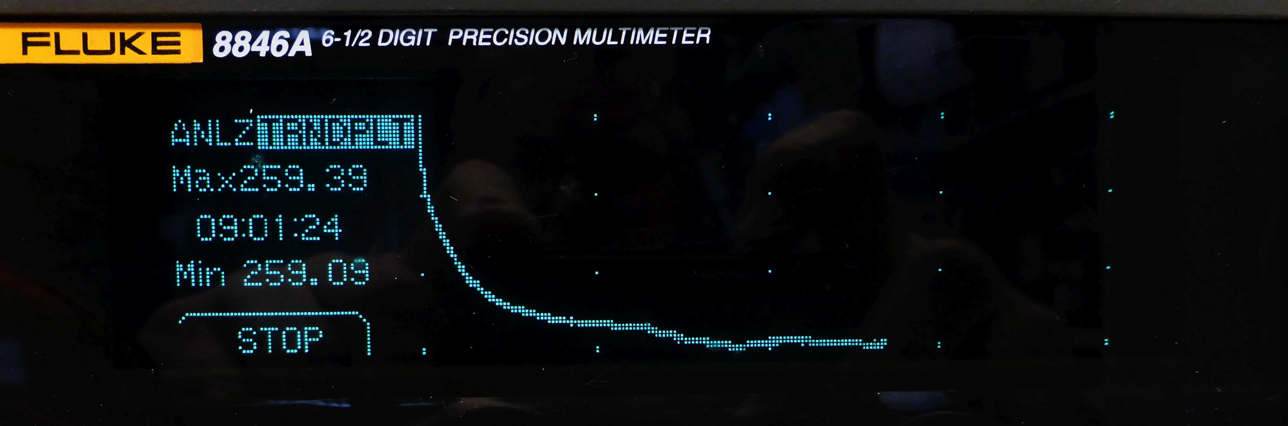
Voltage Drift @ 259.0 V, current drawn was 1.0 mA. First 9 hours after Power On.
A note on Arduino Nano :
We first used the Nano Every, but it turned out, that the 5 V regulator (MPM3610) was somehow unable to supply the AD5667R. Switching to the original Nano (LM1117IMPX-5.0) solved this problem. (Without redesigning the board).
We first used the Nano Every, but it turned out, that the 5 V regulator (MPM3610) was somehow unable to supply the AD5667R. Switching to the original Nano (LM1117IMPX-5.0) solved this problem. (Without redesigning the board).
✈ Share your thoughts
The webmaster does not read these comments regularely. Urgent questions should be send via email.
Ads or links to completely uncorrelated things will be removed.
|
t1 = 7399 d
t2 = 241 ms |
★ ★ ★ Copyright © 2006 - 2026 by changpuak.ch ★ ★ ★
|
|


