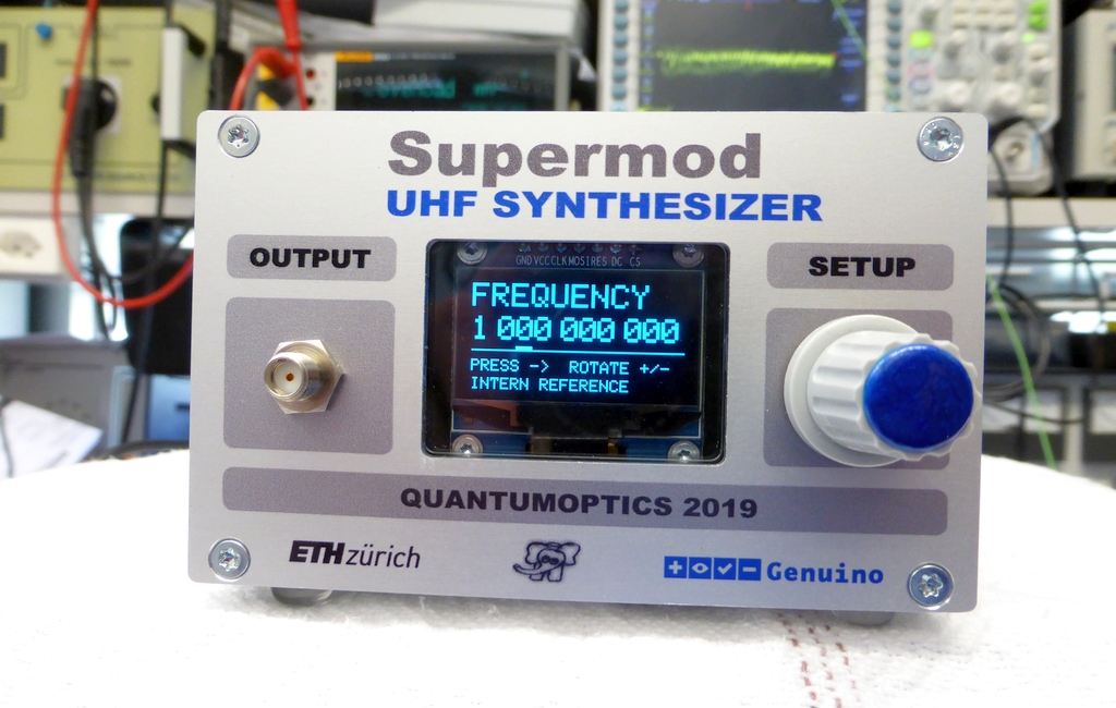
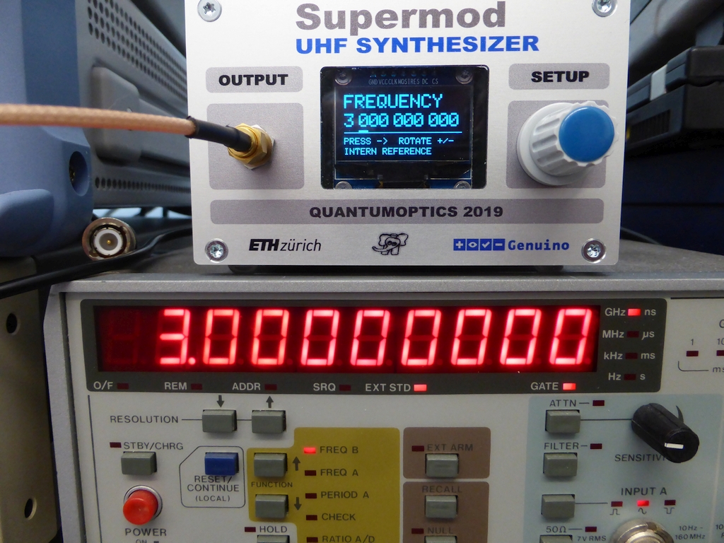
This is a shield to generate an UHF carrier, phaselocked to an internal or external 10 MHz Reference.
Channel spacing is 12.5 kHz (exact), spanning -19.5 up to + 10 dBm in 0.5 dB steps. This is partly an
IPA work, done in 2019 by my apprentice, Mr. Christoph Gisler. IPA means "Individuelle Persönliche
Arbeit" (Individual Personal Work, ≈ final thesis)
✈ Functional Description • Block Diagram
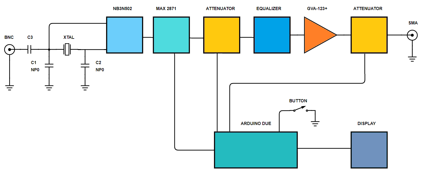
The mastermind of this design is of course the Arduino Due. It handles the user input from the rotary encoder
and displays the status on the 128 x 64 px oled display. The Due also programs the MAX2871 (VCO/PLL), which is the
workhorse of this uhf synthesiser, as well as the two attenuators.
The devices has an onboard 10 MHz crystal oscillator, generating 50 MHz (NB3N502) to serve as a reference clock for the
MAX 2871. If an external 10 MHz is present, it will override the internal clock.
The signal synthesised by the MAX 2871 is then fed into an attenuator (HMC424ALP3E), passes an equaliser (EQY-5-63+),
followed by an amplifier (GVA-123+) and a final attenuator (HMC424ALP3E).
The two attenuators shall allow a frequency dependent loss compensation as well as the attenuation itself. The
equaliser shall help to reduce the amplitude drop at higher frequencies. (FR4 behaves evil above 2 GHz).
And yes, if you attenuate a lot, an amplifier is a nice thing - if you have one (or two).
We even used an external afterburner (ZX60-43-S+, not shown here)
which is specified up to 4 GHz, but goes much higher (MiniCircuits specifies very conservative) - and runs at 5 V - and last but not least, delivers + 12 dBm
up to approx. 5800 MHz into a 50 Ω load.
✈ The workhorse : MAX 2871
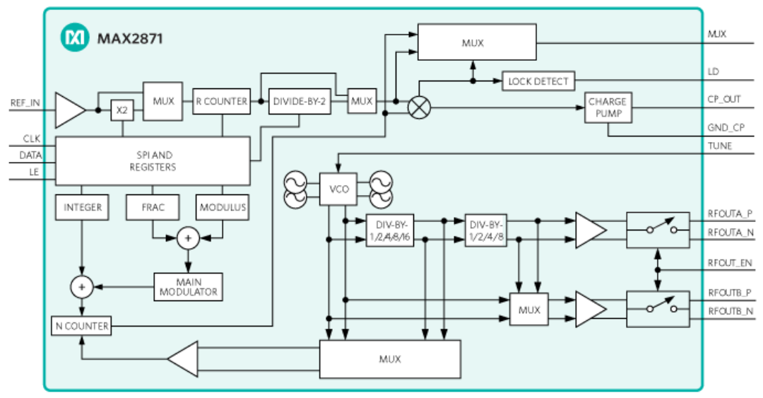
Inside the chip, courtesy of maxim integrated
"The MAX2871 is an ultra-wideband phase-locked loop (PLL)
with integrated voltage control oscillators (VCOs) capable
of operating in both integer-N and fractional-N modes.
When combined with an external reference oscillator and
loop filter, the MAX2871 is a high-performance frequency
synthesizer capable of synthesizing frequencies from
23.5 MHz to 6.0 GHz while maintaining superior phase
noise and spurious performance.
The ultra-wide frequency range is achieved with the
help of multiple integrated VCOs covering 3 GHz to
6 GHz, and output dividers ranging from 1 to 128." says
the datasheet of the MAX2871 by maxim integrated.
As you mayst have seen, there are (digital) frequency dividers involved.
Do not pretend to be surprised, that there are harmonics in the output spectrum.
Instead, use a suiteable lowpass filter if necessary.
MAX 2870 vs. MAX 2871
Maxim integrated offers two similar devices, the MAX2870 as well as the MAX2871. They have slightly different
specifications. As the price is identical, we have no idea, why one should use the MAX2870.
The table below shows the different specifications.
Specification
Condition
MAX2870
MAX2871
Reference Input Frequency (MHz)
Max.
200
210
Maximum PFD Frequency (MHz)
INT mode
FRAC mode
105
50
140
125
3.0 GHZ VCO Open Loop Phase Noise (dBc/Hz)
10MHz offs.
-155.0
-158.0
4.5 GHz VCO Open Loop Phase Noise (dBc/Hz)
10MHz offs.
-151.0
-153.0
6.0 GHz VCO Open Loop Phase Noise (dBc/Hz)
10 MHz offs.
-150.0
-151.0
Integrated RMS Jitter (ps)
0.250
0.200
Normalized In-Band Noise Floor (dBc/Hz)
-266 int
-230 int
1/f Noise (dBc/Hz)
-95.0
-122.0
2nd Harmonics (VCO/2) dBc
-20
-25
Temperature Sensor & ADC
Temp. Compensation from -40C to +85C
Phase Synchronization
Cycle-Slip Reduction and Fast Lock
Mute Until Lock
Muted Output Power
-31.0
-40.0
Total Supply Current at 6 GHz (mA)
162
182
Price / 2500 in CHF (digi-key, 5/2019)
6.912
6.912
Compilation courtesy of Maxim Semiconductor.
✈ 10 MHz Reference
This shield is equipped with a 10 MHz Oscillator (NB3N502) with a times 5 multiplier.
By that, we generate a 50 MHz low jitter reference clock for the MAX 2871.
The input of the oscillator is connected to a bnc connector on the rearpanel. It is always possible
to connect an external reference, there. This signal will override the crystal oscillator.
The display says "INTERN REFERENCE" - this is hard-coded in the sketch and therefore
a static information, depending on the assembly of the crystal oscillator.
Locked to external 10 MHz standard ... Swiss Precision :-)
✈ EE-Sim by Maxim Semiconductor and this Loop-Filter stuff
Maxim Semiconductor offers a free and very helpful tool called EE-Sim. You mayst access
it here.
It is extremely helpful when designing a loop-filter with challenging requirements and beeing built
with real world components.
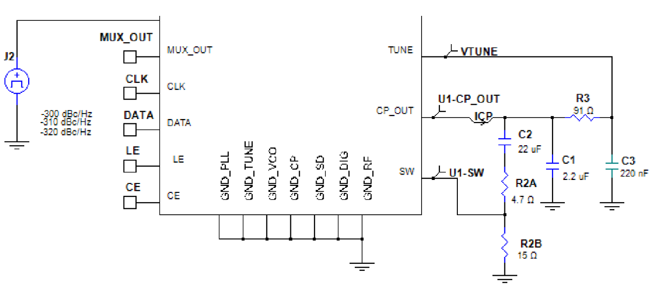
For this design, we demanded a loop-filter with a 1 kHz cut-off frequency (minimum). The EE-Sim tool
tells you, that for this, the minimum charge pump current of 0.32 mA is mandatory. It suggests
a loop filter with the following components :
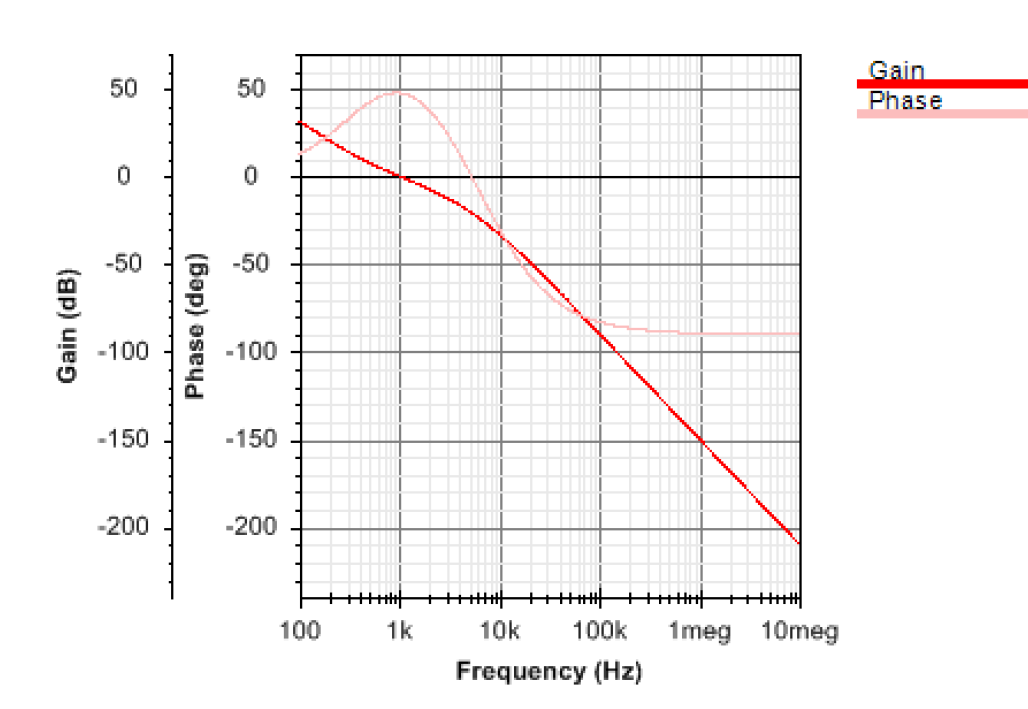
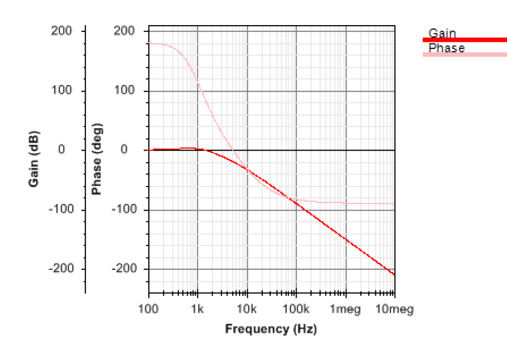
The calculated Gain and Phase of the loop is as follows :
Open Loop Gain / PhaseClosed Loop Gain / Phase
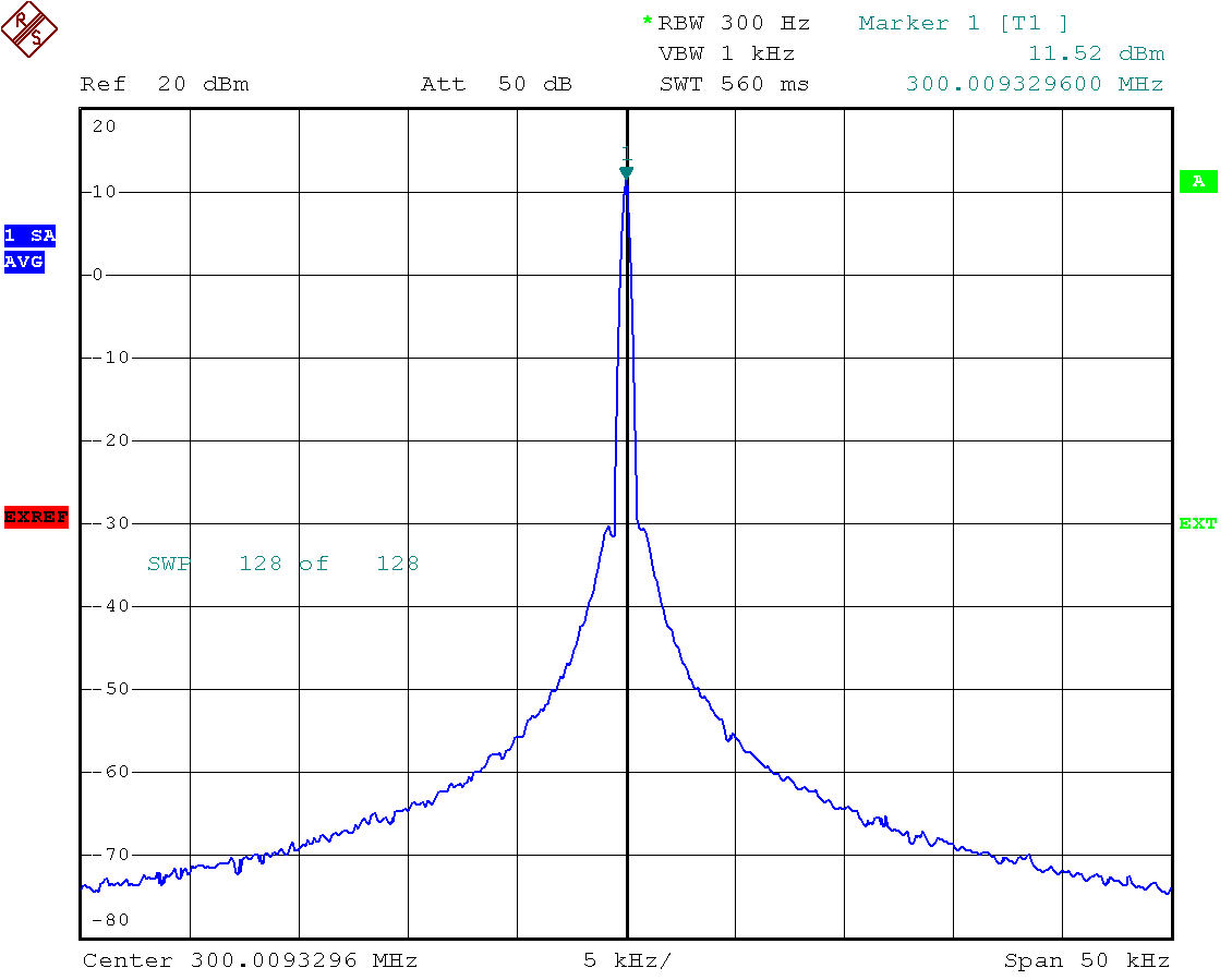
Spectrum at 300 MHz with the above loopfilter using internal reference (uncalibrated)
✈ Downloads
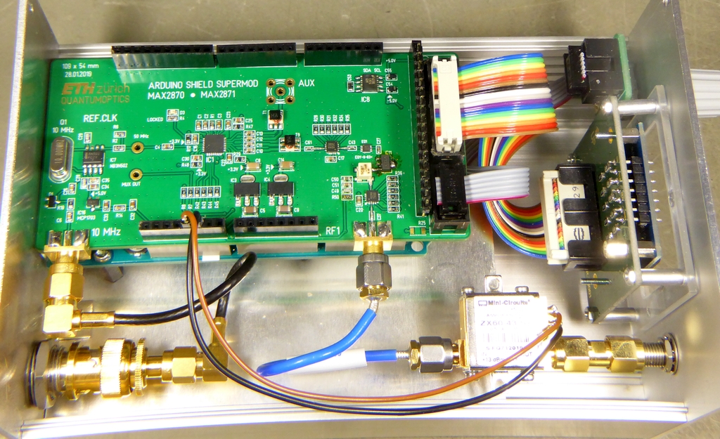
Inside View, A ZX60-43-S+ from MCL gives some extra power ...
✈ Share your thoughts
The webmaster does not read these comments regularely. Urgent questions should be send via email.
Ads or links to completely uncorrelated things will be removed.
 ช้างเผือก