 ช้างเผือก
Categories
Statistics
Since 08.08.2014
Counts only, if "DNT = disabled".
216.73.216.253
216.73.216.253
Counts only, if "DNT = disabled".
216.73.216.253
216.73.216.253
Info

เราจะทำแบบวิศวกรผู้ยิ่งใหญ่

27. July 2026
YOUR OPINION •••
average: 0.001, n: 0

When using this form, your ip is stored in order to avoid multiple voting on the same website. That's it.
When using this form, your ip is stored in order to avoid multiple voting on the same website. That's it.
LNC-1.php 19554 Bytes 04-03-2025 19:13:16
Universal Frequency Converter .:. LNC-Si564-1C
A handy unit with large frequency range
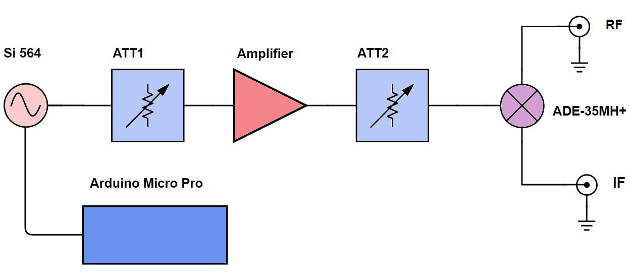
This RF building block consists of a Mixer, a Local Oscillator with Buffer and an Arduino Micro Pro.
It allows single programming on Power Up or constant programming when Sweeping.
It allows frequency translation within a 5 - 3000 MHz range.
✈ Specifications :
| RF Range [MHz] | 5 - 3500 | ADE-35MH+ |
| LO Range [MHz] | 0.2 - 2500 | Si 564 with Amplifier delivers + 13 dBm |
| IF Range [MHz] | 5 - 2500 | - |
| Max. Input Power | 200 mW, + 23 dBm | @ RF Input, Damage Level of Mixer !!! |
| Conversion Loss [dB] | 8.0 ± 1.0 | - |
| Power Consumption | + 7.5 V, 500 mA | - |
✈ Functional Description • The Building Blocks
The heart of this converter is the Si 564 from SILABS. It is an Ultra Low Jitter I2C Programmable XO (90 fs), 0.2 to 3000 MHz. We use the (Part Number: 564AAAA000112ABG) here. It has two LVPECL outputs which are summed up by a TCM1-83x-1+ transformer. (From Mini Circuits).
The Programming is done by an Arduino Micro Pro from SparkFun.
Following the XO, there is an attenuator (ATT1), an amplifier (GALI-2+) followed by another attenuator (ATT2). This is to ensure, that the LO is more or less + 13 dBm.
✈ Si 564 from SILABS
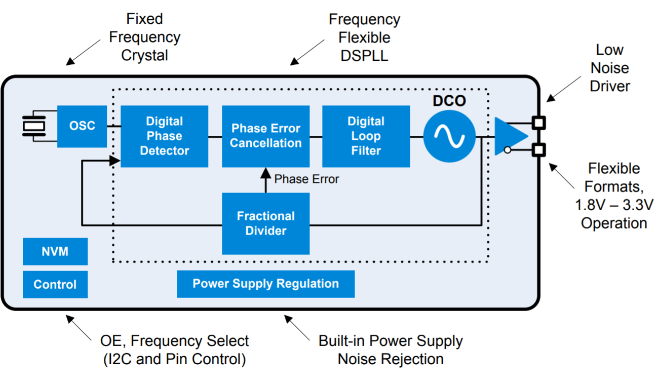
This is the heart of our converter. Not only because it provides the "heart-beat", but also because it provides an ultra-low jitter, low phase noise clock at any output frequency. The device is user-programmed via simple I2C commands to provide any frequency from 0.2 to 3000 MHz with <1 ppb resolution and maintains exceptionally low jitter for both integer and fractional frequencies across its operating range. The Si564 offers excellent reliability and frequency stability as well as guaranteed aging performance. Says the datasheet. And we see it that way too.
✈ Printed Circuit Board • Assembly

The pcb, visualised by Beta Layout
The board is made of FR4 and it is 1.55 mm thick. It is single sided, the bottom layer is GND only.
RF design rules have been applied. A 50 Ω trace is 1.5 mm wide and has a gap of 0.345 mm. The RF corners
have an X/D ratio of 69.6 %. We used
this calculator for the corners.
We use 1206, 0603 and 0402 components here.
Depending on the frequency of the Local Oscillator, different attenuators are to be used to achieve + 13 dBm for the mixer.
We suggest the following values :

Output Voltage swing of the Si564, Drawing courtesy of SILABS, see datasheet page 6
And yes, the situation gets worse with the transformer, because it is also frequency - dependant.
We use 1206, 0603 and 0402 components here.
Depending on the frequency of the Local Oscillator, different attenuators are to be used to achieve + 13 dBm for the mixer.
We suggest the following values :
| LO Range [MHz] | ATT 1 [dB] | ATT 2 [dB] |
| < 1000 | 3 | 1 |
| 1000 - 1500 | 3 | 0 |
| 1500 - 1750 | 2 | 0 |
| 1750 - 2000 | 2 | 0 |
| 2000 - 2250 | 1 | 0 |
| 2250 - 2500 | 1 | 0 |
Output Voltage swing of the Si564, Drawing courtesy of SILABS, see datasheet page 6
And yes, the situation gets worse with the transformer, because it is also frequency - dependant.
✈ Case
The case is milled from aluminium. Coated with nickel to ensure high conductivity. The case was
not available at the time this website was created. See the download section for the drawing.
✈ Downloads


✈ Arduino Sketch - The Code
Double click on code to select ...
/* /////////////////////////////////////////////////////////////////////
Sparkfun Pro Micro Sketch for LNC-Si564-1C
Software Version 1.0,
09.09.2019 by Alexander Sse Frank

HELFUL :
https://learn.sparkfun.com/tutorials/pro-micro--fio-v3-hookup-guide/all
//////////////////////////////////////////////////////////////////////*/

#include <Wire.h>


// SI564 VARIABLES / CONSTANTS
unsigned long long F_VCO_MIN = 10800000000 ;
unsigned long long F_VCO_MAX = 13122222022 ;
unsigned long long F_OUT_MIN = 19999999 ;
unsigned long long F_OUT_MAX = 2500000001 ;
unsigned long long F_OUT = 500000000 ;
const byte Si564_Address = 0x55 ;

const int PullUpC = 4 ;
const int PullUpD = 8 ;


void setup()

{
pinMode( PullUpC, OUTPUT ) ;
pinMode( PullUpD, OUTPUT ) ;
digitalWrite( PullUpC, HIGH );
digitalWrite( PullUpD, HIGH );

delay(1999) ;

Wire.begin() ;
Serial.begin(9600) ;

UpdateFreq(F_OUT) ;

delay(999) ;

UpdateFreq(F_OUT) ;
}

void loop()
{
// GO SLEEP
}

void UpdateFreq( unsigned long long F_OUT)
{
// NOTE: SIMPLIFIED CALCULATIONS, AS F_MIN > 6.4 MHz,
// LSDIV IS ALWAYS 1, 0x00

if (F_OUT < F_OUT_MIN) F_OUT = F_OUT_MIN ;
if (F_OUT > F_OUT_MAX) F_OUT = F_OUT_MAX ;

byte Aux = 0x00 ;
unsigned long HSDIV ;
unsigned long XTAL = 152600000 ; // Hz
double FBDIV ;
unsigned long INTEGER ;
unsigned long long FRACTION ;
unsigned long long F_VCO ;
FBDIV = (double)(F_VCO_MIN * 1.0 / F_OUT );
HSDIV = (int)(FBDIV + 0.5) ;
if ((HSDIV > 32) && (HSDIV % 2)) HSDIV += 1 ;
// MIN MAX VALUE
if (HSDIV < 4) HSDIV = 4 ;
if (HSDIV > 2046) HSDIV = 2046 ;
F_VCO = HSDIV * F_OUT ;
FBDIV = (double)(F_VCO * 1.0 / XTAL) ;
INTEGER = FBDIV ;   // FLOOR :-)
FRACTION = 4294967295.0 * (double)(FBDIV - INTEGER) ;
// Get Device Ready for Update
// Set page register to point to page 0
Si564_Write_Byte( 255, 0x00) ;
// Disable FCAL override
Si564_Write_Byte( 69, 0x00) ;
// Synchronously disable output
Si564_Write_Byte( 17, 0x00) ;
// HSDIV [7:0]
Aux = HSDIV & 0xFF ;
Si564_Write_Byte( 23, Aux) ;
// LSDIV[2:0]; HSDIV[10:8]
Aux = (HSDIV >> 8) & 0x07 ;
Si564_Write_Byte( 24, Aux) ;
// FBDIV [7:0]
Aux = FRACTION & 0xFF ;
Si564_Write_Byte( 26, Aux) ;
// FBDIV [15:8]
Aux = (FRACTION >> 8 ) & 0xFF ;
Si564_Write_Byte( 27, Aux) ;
// FBDIV [23:16]
Aux = (FRACTION >> 16 ) & 0xFF ;
Si564_Write_Byte( 28, Aux) ;
// FBDIV [31:24]
Aux = (FRACTION >> 24 ) & 0xFF ;
Si564_Write_Byte( 29, Aux) ;
// FBDIV [39:32]
Aux = INTEGER & 0xFF ;
Si564_Write_Byte( 30, Aux) ;
// FBDIV [42:40]
Aux = (INTEGER >> 8 ) & 0x07 ;
Si564_Write_Byte( 31, Aux) ;
// Start FCAL using new divider values
Si564_Write_Byte( 7, 0x08) ;
// Synchronously enable output
Si564_Write_Byte( 17, 0x01) ;
}

void Si564_Write_Byte( byte Register, byte Value)
{
byte Error = 0x00 ;
Wire.beginTransmission(Si564_Address);
Wire.write(Register);
Wire.write(Value);
Error = Wire.endTransmission();
SerialHexOutput(Value) ;
/*
switch (Error)
{
case 0 : Serial.println("0:success");
break;
case 1 : Serial.println("1:data too long to fit in transmit buffer");
break;
case 2 : Serial.println("2:received NACK on transmit of address");
break;
case 3 : Serial.println("3:received NACK on transmit of data");
break;
case 4 : Serial.println("4:other error");
break;
}
*/
}

void SerialHexOutput(byte value)
{
Serial.print("0x");
if (value < 0x10) Serial.print("0");
Serial.println(value,HEX);
}


// /////////////////////////////////////////////////////////////////////
// END OF FILE
// /////////////////////////////////////////////////////////////////////
✈ Performance
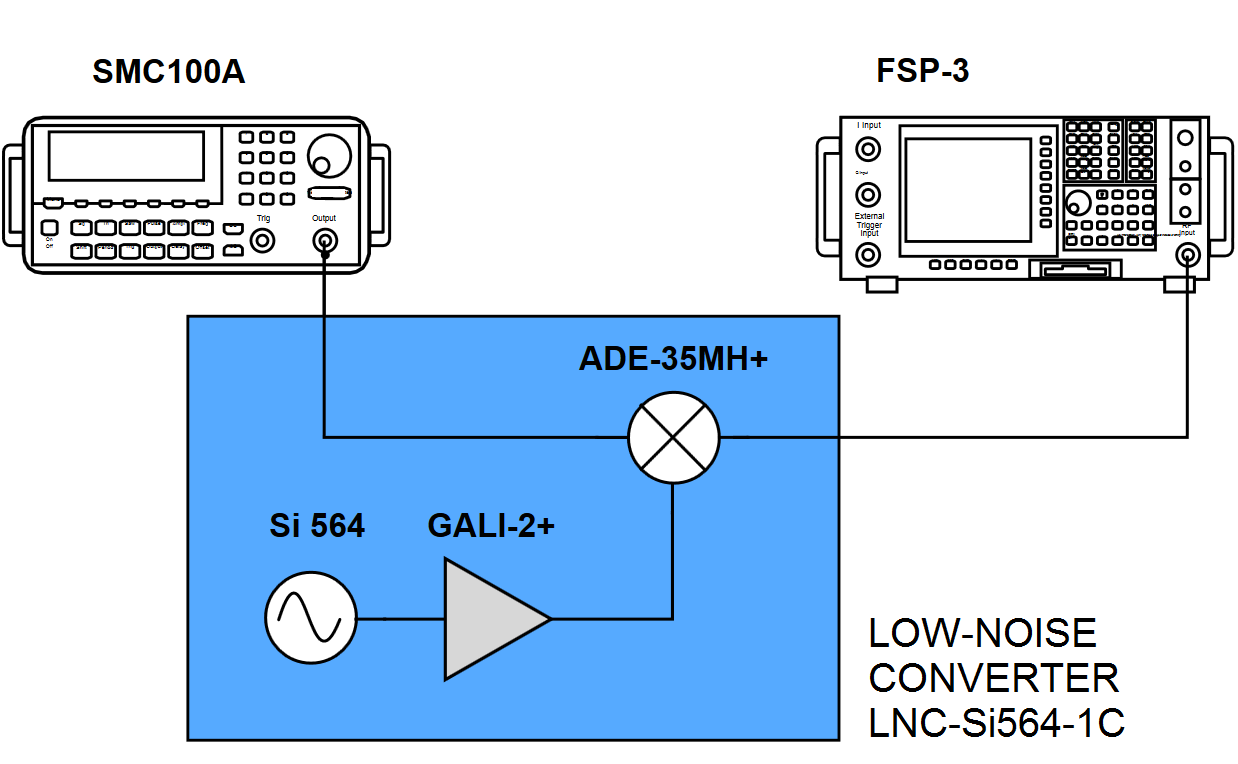
Test - Setup, we used 2 x 100 mm Multiflex 86 from Huber & Suhner for the connections
To test this thing, we programmed the LO to 500 MHz. The RF source is a SMC100A from Rohde & Schwarz, running at 499 MHz. Level is -17 dBm. The measurements below are made at the IF output of the mixer. With an FSP-3 from Rohde & Schwarz.
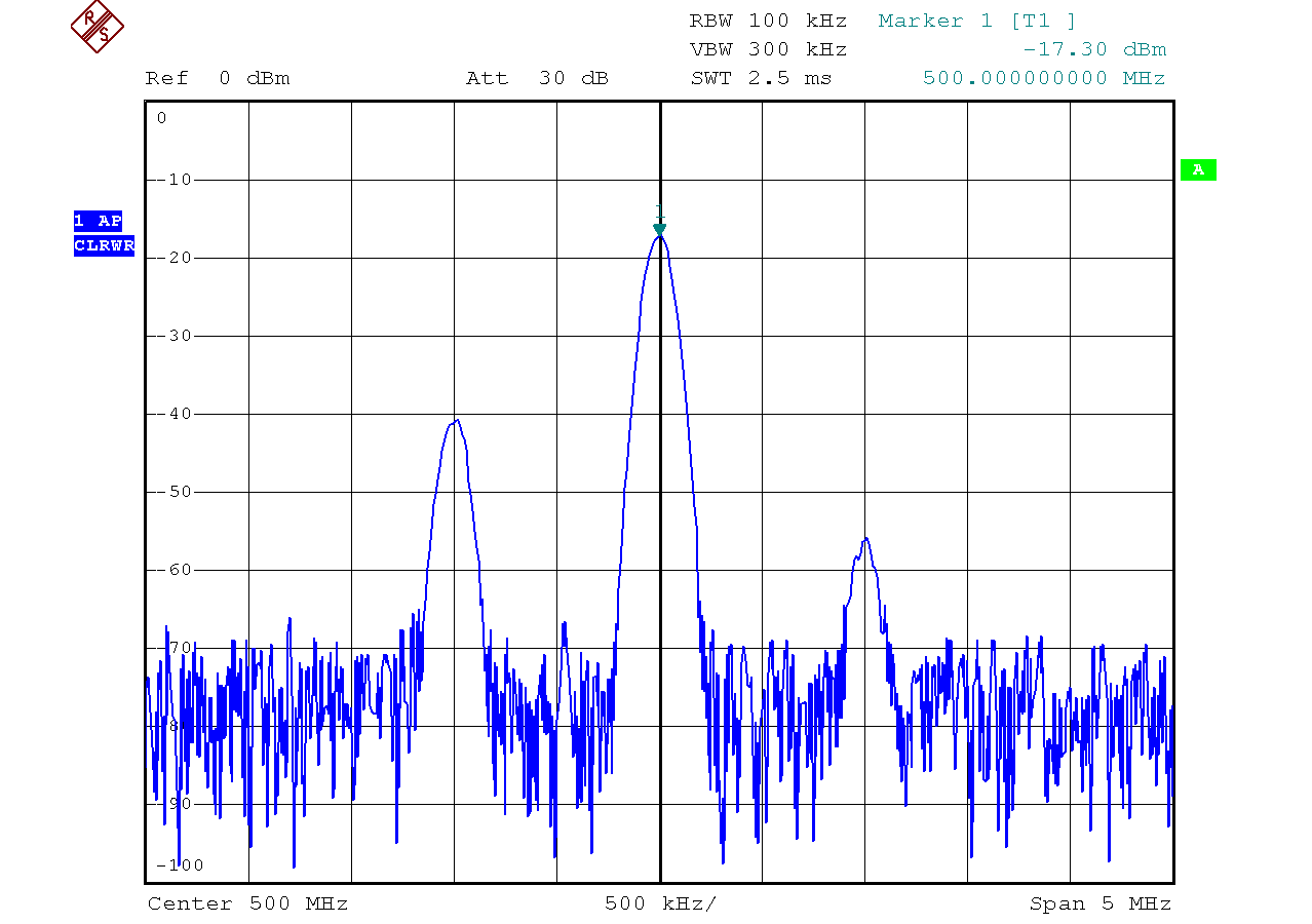
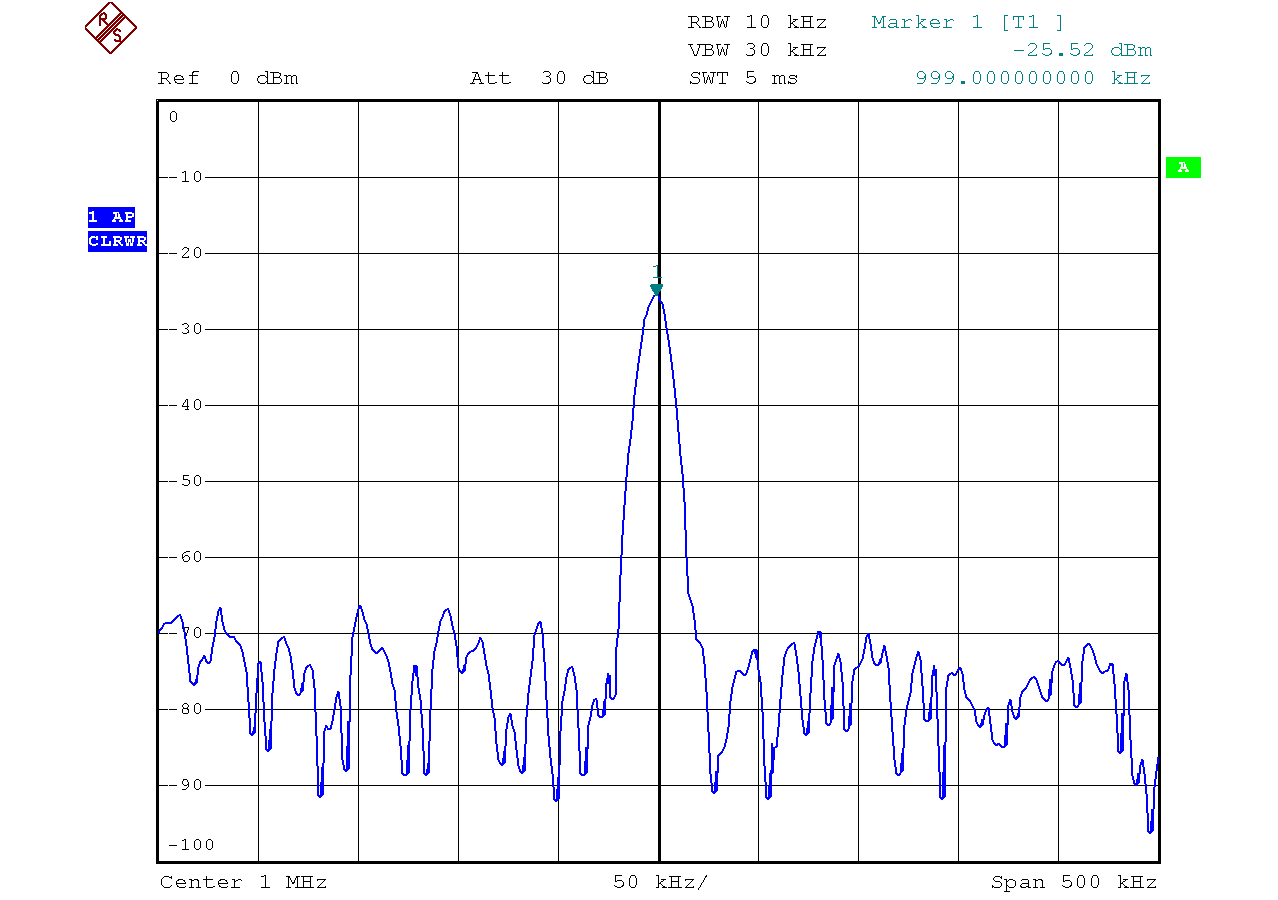
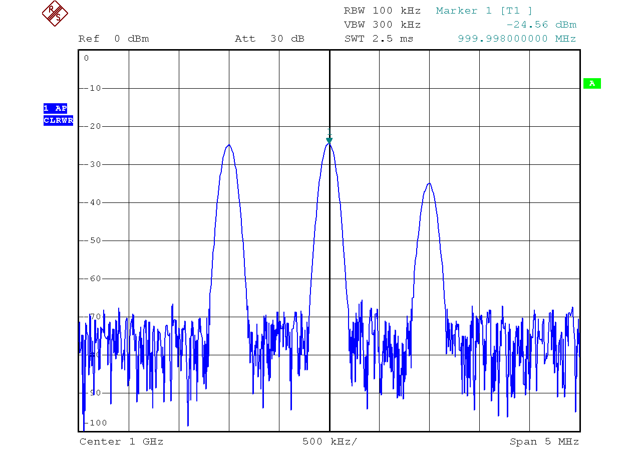

Fig. 1 .:. RF & LO - Feedthrough
The RF & LO Feedthrough. At the IF output, the LO appears approx. 30 dB attenuated and the RF can be seen approx. 23 dB attenuated.
Fig. 2 .:. IF - downconverted
The downconverted IF has a level of - 25.5 dBm. As we used - 17 dBm for the RF, the conversion loss is about 8.5 dB. This includes the coaxial cables as well as the copper traces of the converter.
Fig. 3 .:. IF - upconverted
The upconverted IF has a level of approx. - 25 dBm. As we used - 17 dBm for the RF, the conversion loss is about 8 dB. This includes the coaxial cables as well as the copper traces of the converter. We can also see the harmonic of the LO at 1000 MHz (-24.56 dBm). And another mixing product at 1001 MHz.
✈ General Advice on Operating RF-Mixers
An RF-Mixer is a 50 Ω component. It is designed to work in a 50 Ω environment.
That means that it performs best, when the impedances at the RF-Input and at the IF-Output
are 50 Ω. This termination should be as broadband as possible.
It is very likely, that filters are connected to the input / output of this converter. This reduces the termination seen by the mixer to the passband of those filters. Now evil things may happen, as the stopband of the filter is suiteable to reflect frequencies outside back into the mixer. This can be avoided by using reflectionless filters or as a "quick and dirty" hack, 6 dB Attenuators (which match almost anything to 50 Ω).
It is very likely, that filters are connected to the input / output of this converter. This reduces the termination seen by the mixer to the passband of those filters. Now evil things may happen, as the stopband of the filter is suiteable to reflect frequencies outside back into the mixer. This can be avoided by using reflectionless filters or as a "quick and dirty" hack, 6 dB Attenuators (which match almost anything to 50 Ω).
✈ Credits • Note of Thanks
We would like to thank the staff of Computer Controls AG (Switzerland) for their efforts to supply us
(our research group at ETH zürich)
with free samples.
ขอขอบพระคุณทุกท่าน.
ขอขอบพระคุณทุกท่าน.
Better than Birthday and Christmas together :-)
✈ Share your thoughts
The webmaster does not read these comments regularely. Urgent questions should be send via email.
Ads or links to completely uncorrelated things will be removed.
|
t1 = 7319 d
t2 = 231 ms |
★ ★ ★ Copyright © 2006 - 2026 by changpuak.ch ★ ★ ★
|

|