 ช้างเผือก
Categories
Statistics
Since 08.08.2014
Counts only, if "DNT = disabled".
216.73.216.253
216.73.216.253
Counts only, if "DNT = disabled".
216.73.216.253
216.73.216.253
Info

เราจะทำแบบวิศวกรผู้ยิ่งใหญ่

27. July 2026
YOUR OPINION •••
average: 4.500, n: 2

When using this form, your ip is stored in order to avoid multiple voting on the same website. That's it.
When using this form, your ip is stored in order to avoid multiple voting on the same website. That's it.
PhotodiodeOpampAmplifier.php 8817 Bytes 04-03-2025 19:13:21
Photodiode Opamp Amplifier (Transimpedance Ampl.)
Circuits and Calculation
✈ How not to do it
As we know from the above websites (regarding to the menue), the Photodiode creates a current. One could now
have the idea to use a resistor to create a voltage which then is amplified by an Opamp.
A circuit could look like this :
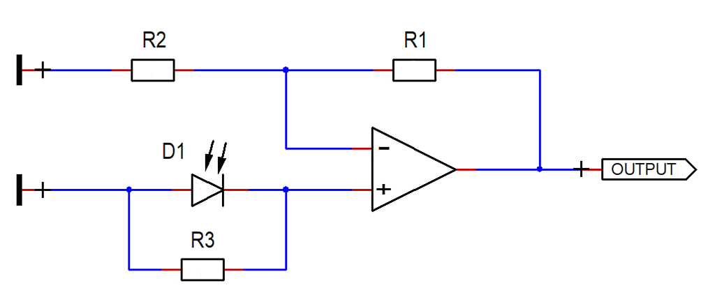
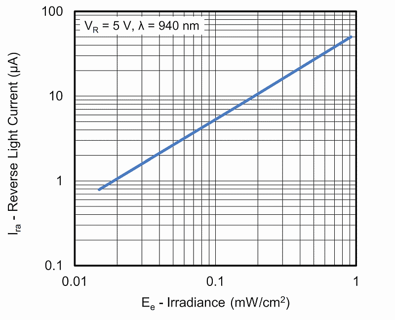 This circuit does work, but as the graph to the left suggests, the output voltage is
strongly nonlinear with respect to the light applied to the photodiode.
This circuit does work, but as the graph to the left suggests, the output voltage is
strongly nonlinear with respect to the light applied to the photodiode.
It is therfore not suggested.
Drawing courtesy of Vishay
This circuit does work, but as the graph to the left suggests, the output voltage is
strongly nonlinear with respect to the light applied to the photodiode.It is therfore not suggested.
Drawing courtesy of Vishay
✈ A better way : Transimpedance Amplifier
A better way is the use of a Transimpedance Amplifier. That circuit does convert
a current into a voltage. As the photocurrent is linear to the applied light, the output
voltage is also linear with respect to the light. A circuit could look like this :
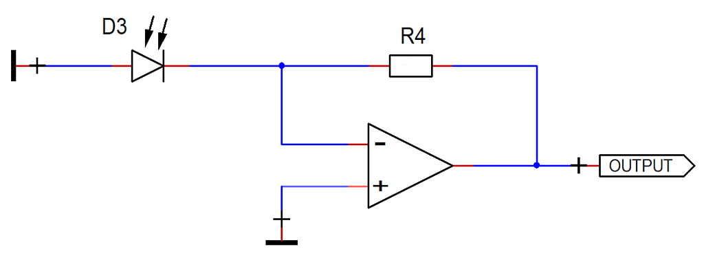
Here the phtocurrent is fed into the inverting input of the Opamp. Depending on the orientation of the photodiode, the output can be negative or positive. (The circuit shown produces a positive output, when light shines on the photodiode.)
Here the phtocurrent is fed into the inverting input of the Opamp. Depending on the orientation of the photodiode, the output can be negative or positive. (The circuit shown produces a positive output, when light shines on the photodiode.)
✈ Upgrade #1 : Limiting the Bandwidth
Opamps with high gain mayst oscillate. A high bandwidth also comes with a lot of noise.
Therefore it mayst be necessary to limit the bandwidth. This can easily be achieved
with a shunt capacitor across the feedback resistor. A circuit could look like this :
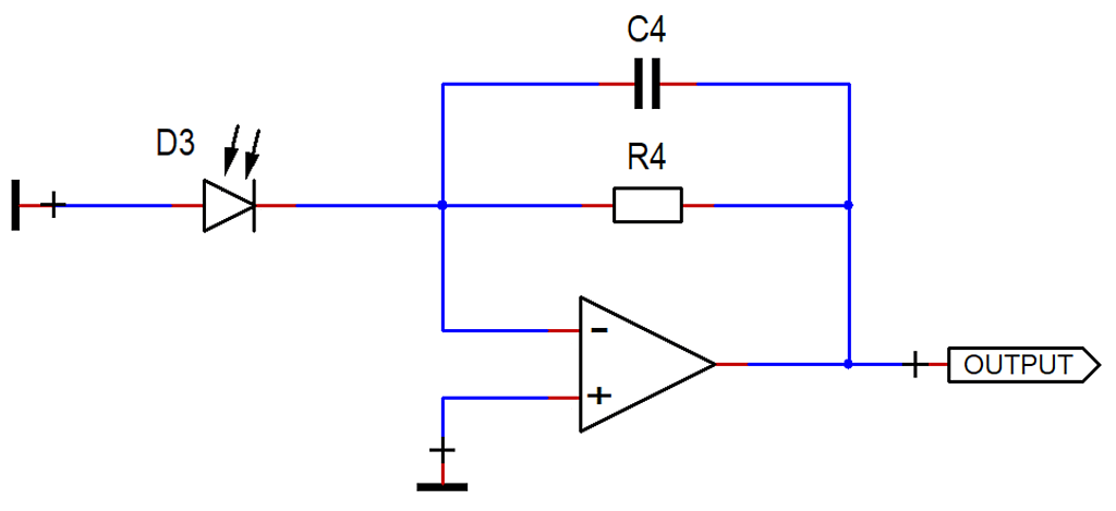
Here C4 parallel R4 is responsible for the reduction of the Gain at higher frequencies. The Output Voltage, which is :
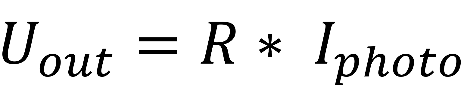
must now be looked at in three different regions.
If the frequency is very small, the capacitor can be neglected. If the frequency is large, the resistor can be neglected. And at the cutoff frequency - where Gain becomes 50 % - the Impedance of the capacitor becomes equal to the Impedance of the resistor. We can therefore calculate the value of the capacitor with the well known formula :
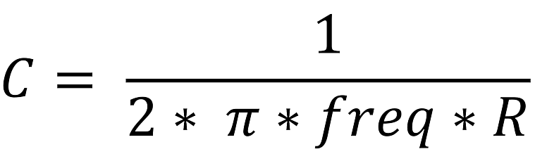
Exempli gratia :
An Optical Power P = 1 mW shall produce an Output Voltage of 1 V.
The upper corner frequency shall be 1 kHz.
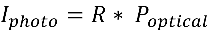
With an R = 0.5 A/W, the Photodiode delivers a Photocurrent of 0.5 mA.
(The R value describes the Responsivity and can be found in the Datasheet)
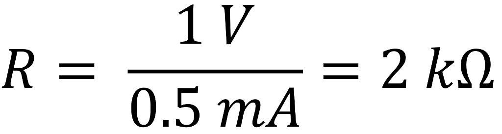
This R describes the Resistance. Do not mix them up !!!
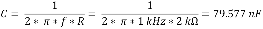
In real life, I would use 82 nF (E12 value) and have a slightly lower corner frequency.
Here C4 parallel R4 is responsible for the reduction of the Gain at higher frequencies. The Output Voltage, which is :
must now be looked at in three different regions.
If the frequency is very small, the capacitor can be neglected. If the frequency is large, the resistor can be neglected. And at the cutoff frequency - where Gain becomes 50 % - the Impedance of the capacitor becomes equal to the Impedance of the resistor. We can therefore calculate the value of the capacitor with the well known formula :
Exempli gratia :
An Optical Power P = 1 mW shall produce an Output Voltage of 1 V.
The upper corner frequency shall be 1 kHz.
With an R = 0.5 A/W, the Photodiode delivers a Photocurrent of 0.5 mA.
(The R value describes the Responsivity and can be found in the Datasheet)
This R describes the Resistance. Do not mix them up !!!
In real life, I would use 82 nF (E12 value) and have a slightly lower corner frequency.
✈ Upgrade #2 : Adding reverse Bias
Adding a reverse Bias to the Photodiode may give some advantages, as
• The Capacity of the Photodiode is reduced -> higher Frequency
• The Depletion Area is enlarged -> higher Responsivity
A circuit could look like this :
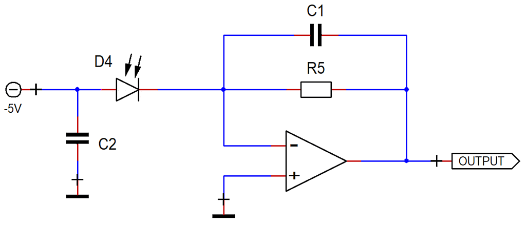
Here we connected the Anode of the Photodiode to a negative Supply of -5V.
• The Capacity of the Photodiode is reduced -> higher Frequency
• The Depletion Area is enlarged -> higher Responsivity
A circuit could look like this :
Here we connected the Anode of the Photodiode to a negative Supply of -5V.
✈ Upgrade #3 : High Bandwidth and high Gain
The Gain - Bandwidth - Product of an Opamp is a fixed number. In case you
need a high Gain and a high Bandwidth, it is recommended to split the Gain onto
several Opamps. Instead of one Opamp with a Gain of V = 100, you mayst use two
of them with a Gain of V = 10. This would increase the Bandwidth by a factor of 10.
See this website for more information.
✈ Downloads


✈ Share your thoughts
The webmaster does not read these comments regularely. Urgent questions should be send via email.
Ads or links to completely uncorrelated things will be removed.
|
t1 = 7319 d
t2 = 219 ms |
★ ★ ★ Copyright © 2006 - 2026 by changpuak.ch ★ ★ ★
|

|