 ช้างเผือก
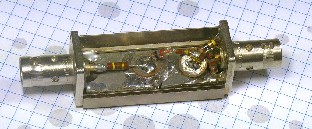
Categories
Statistics
Since 08.08.2014
Counts only, if "DNT = disabled".
216.73.216.253
216.73.216.253
Counts only, if "DNT = disabled".
216.73.216.253
216.73.216.253
Info

เราจะทำแบบวิศวกรผู้ยิ่งใหญ่

27. July 2026
YOUR OPINION •••
average: 7.800, n: 5
When using this form, your ip is stored in order to avoid multiple voting on the same website. That's it.
When using this form, your ip is stored in order to avoid multiple voting on the same website. That's it.
Diode_Detectors.php 8512 Bytes 04-03-2025 19:12:41
DIY Diode RF Detectors
Germanium • Schottky
✈ Single Diode Detector Circuit
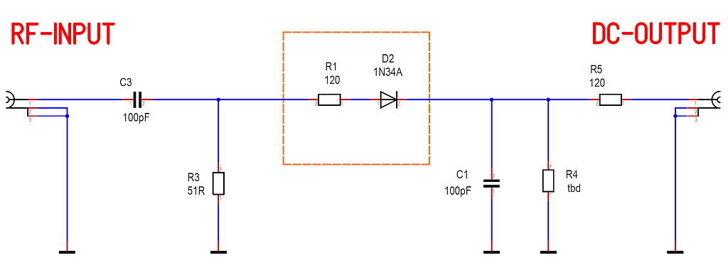
This is the single diode circuit. Use it when the diode is super-expensive or the power is "high". The signal is ac-coupled via C3. A 50 Ω termination is ensured by R3. R1 and D2 perform the rectification. The positive peak value is stored in C1. It is slowly discharged by R4 (tbd). Depending on the use of your diode detector, R4 has to be chosen therfore. that the af frequency has low distortion.
✈ Twin Diode Detector Circuit
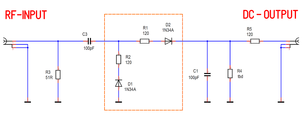
The circuit used here. With two diodes, you can create a voltage doubler. This comes in handy, when the signal to be measured is low in amplitude.
✈ Diode Selection
For RF rectification a fast switching capability is mandatory.
In a p–n diode (e.g. 1N4148), the reverse recovery time can be in the order of several µs
to less than 100 ns for fast diodes, and it is mainly limited by the diffusion capacitance caused by
minority carriers accumulated in the diffusion region during the conducting state.
Schottky diodes are significantly faster, since they are unipolar devices and their speed is only limited by the junction capacitance. The switching time is approx. 100 ps for the small-signal diodes.
Schottky diodes are significantly faster, since they are unipolar devices and their speed is only limited by the junction capacitance. The switching time is approx. 100 ps for the small-signal diodes.
| Type | Forw. Volt. [mV] | Capacity [pF] |
| HP 5082-2800 | 380 | 2.0 |
| 1N5711 | 410 | 2.0 |
| BAT83S | 410 | 1.6 |
| 1N5712 | 550 | 1.2 |
| HP5082-2811 | 410 | 1.2 |
| HP5082-2835 | 340 | 1.0 |
✈ AM-Demodulator / RF Detector / Demodulator probe for DMM
We use the Twin Diode Detector Circuit here. Assembly : R3 = 51 Ω, C3 = 100 nF, R1, R2 = 51 Ω,
D1, D2 = 1N5711, C1 = 100 nF, R4 = 10 kΩ, R5 = 51 Ω.
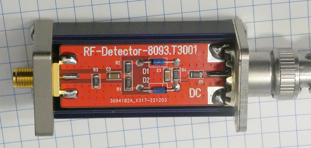
The Engineering Sample, mounted in a SucoBox
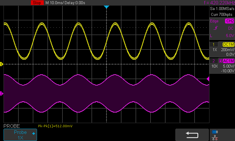
Carrier was 1 MHz, + 6 dBm, Amplitude modulated, 40 Hz AF
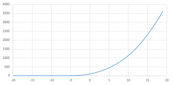
Output [mV] vs. Input level [dBm]. Useful for "higher" levels.
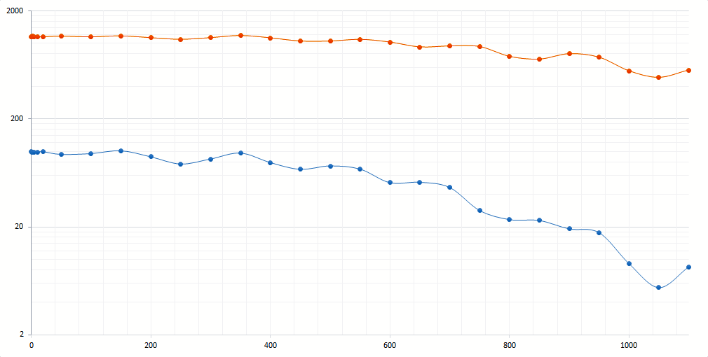
Output [mV] vs. Frequency [MHz]. Level was 0 dBm (blue) and + 10 dBm (orange).
The Engineering Sample, mounted in a SucoBox
Carrier was 1 MHz, + 6 dBm, Amplitude modulated, 40 Hz AF
Output [mV] vs. Input level [dBm]. Useful for "higher" levels.
Output [mV] vs. Frequency [MHz]. Level was 0 dBm (blue) and + 10 dBm (orange).
✈ Downloads


✈ Similiar Projects
For a lower level, check out the AD8307 Logarithmic Amplifier
The Levelmod has different sensors as well as an analog output.
The Levelmod has different sensors as well as an analog output.
✈ Share your thoughts
The webmaster does not read these comments regularely. Urgent questions should be send via email.
Ads or links to completely uncorrelated things will be removed.
|
t1 = 7319 d
t2 = 250 ms |
★ ★ ★ Copyright © 2006 - 2026 by changpuak.ch ★ ★ ★
|

|