 ช้างเผือก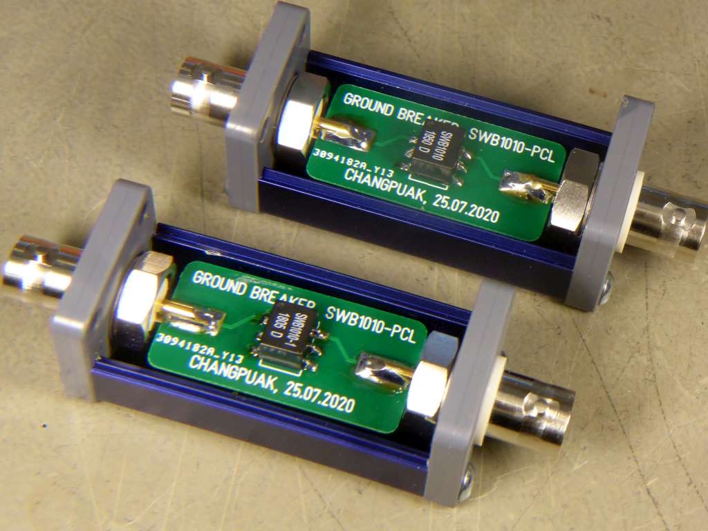
Categories
- Hua Hin Weather Station 🌤
- Projects (Antiques) 🦖
- Micro Projects • Tools 🪓
- Atmega8 LED Panelmeter (U,I,°C,°F)
- Corona Customer Counter for a shop/place
- LCD Adapter • Interface
- Microphone Preamplifier
- ROTARY ENCODER (STEC11B03)
- SDRSharp and a DVB-T stick : a 20 EUR Spectrum Analyser ?
- UART - RS232 Bridge (ST232CDR)
- UART - USB Bridge (MCP2200)
- UART - ETHERNET Bridge (LANTRONIX XPORT)
- USB - InfraRed Transceiver
- USB - PLL / DDS - Interface
- Arduino Projects 🛸
- Spectrum Analyzer • Measurement Receiver ➜
- A DC-199 MHz Spectrum Analyser 'VISIONARY' with Si4432
- A 15-2700 MHz Spectrum Analyser with the RF Explorer 3G+
- Levelmod - A DC to Daylight Microwave Powermeter
- Micro Smart Power Sensor - with AD8319, TMP101
- Polarmod - An I-Q-Processor with the AD9958
- VHF Airband Receiver with Si570 and AD8361
- Wacharamod - An FM Stereo Receiver with the TEA5767
- Wanmod, A Frequency Selective Levelmeter, 29.999 MHz
- Network Analyzer ➜
- Frequency Counter • Frequency Standard ➜
- Low Frequency (AF) Generators ➜
- High Frequency (RF) Synthesizer ➜
- Kumod - 1 MHz ... 200 MHz Synthesiser with the AD9958
- Micromod - A 220 MHz Synthesizer with the Si570
- Macromod - A 850 MHz Synthesizer with the LMK61E2
- Ningmod - A RF Synthesizer with the AD9953 + co-workers
- Sathanimod - an FM Radiostation with the Si4713
- Supermod - A 23.5 - 6000 MHz Synthesizer with the MAX2871
- Teramod - A 2 to 15 GHz Synthesizer
- Ultramod - A 9.9 - 3200 MHz Synthesizer with the Si564
- Power Supplies • Voltage Standards ➜
- Measurement Devices • U • I • P • R • T ➜
- RF Switches • Attenuators ➜
- Component Tester ➜
- Environmental Test System - Madimod ➜
- P-I-D and other Controllers ➜
- Other Shields for Arduino ➜
- Shield BHUMI : A Voltage Standard, programmeable
- CALC-DUINO, a simple Pocket Calculator Shield (MAX7219)
- CLOCK-DUINO, a clock, to be shown to my teachers :-)
- DCF-77 Synthesizer. With Arduino. Aka "TimeDuino"
- Shield LEO : SMS on Power down
- Shield MARCELLA : Control your Laboratory Devices
- Shield NRVD : Dual UHF Power Meter
- Shield RENÉ : Reference Voltage Source, aka REFDUINO
- Shield TANACHAI : A Transistor Curve Tracer
- Shield TOBI : A 60 MHz, 80dB Scalar Network Ananlyzer
- Add-on BRUNO : Universal Battery Tester (Charge/Discharge)
- Arduino Final Projects : IPA's ➜
- Arduino Knowledgebase ➜
- What's All This '...mod' Stuff, Anyhow ?
- Additional Components for all '...mod' things
- Spectrum Analyzer • Measurement Receiver ➜
- Bluepill • Blackpill Projects 🛸
- Teensy Projects 🛸
- Raspberry Pi Projects 🛸
- Python Lab Experiments 🐍
- Power Supplies ⚡
- Calculations • Design • Design Examples
- Measurements • Characterisation (Noise, Ripple)
- Anything Supplymod (mostly using Arduino Nano Every)
- Anything PETH (no Microprofessor)
- PETH-6 Power Supply • ± 15 V, 100 mA
- PETH-6 Power Supply • +7.5 V, for Arduino / Genuino
- PETH-20 Power Supply • ± 15 V, 600 mA
- PETH-30 Power Supply
- PETH-40 B3 Power Supply ±15V, 1200 mA
- PETH-40-HAM Power Supply • ± 15 V, 1.5 A
- PETH-49 Power Supply • 1 ... 19 V, 2 A
- PETH-200V - High Voltage Power Supply
- PETH-581 Power Supply • Buck Conv. with Linear Afterburner
- PETH-1074 Power Supply • Step-Down with an LT1074
- PETH-8093 Power Supply • Step-Down and linear regulation
- PETH-9910 Power Supply • 8 ... 16 V, 10 A
- Anything High Voltage
- Anything else
- AC Power Source. 310 V, 2 A with an Arduino Nano Every, SCPI
- Amplifiers • Calculations
- Audio Amplifier ➜
- Amplifier Calculations • Design ➜
- Low Noise Amplifier ➜
- Measurement Amplifier ➜
- Universal Amplifier, using Mini Circuits Components ➜
- SOT-115 J-9 Power Modules ➜
- VHF/UHF Power Amplifier with the BGD 804 - 860 MHz, 24 V
- VHF/UHF Power Amplifier with the BGY 588N - 550 MHz, 24 V
- VHF/UHF Power Amplifier with the QPA 3314 - 1794 MHz, 24 V
- VHF/UHF Power Amplifier with the QPA 3316 - 1794 MHz, 24 V
- VHF/UHF Power Amplifier with the TAT 8888 - 1000 MHz, 24 V
- VHF/UHF Power Amplifier with the RFPD 3580 - 1218 MHz, 24 V
- Even Bigger Power Modules ➜
- Shortwave Amplifier ➜
- Opamp Circuits • Knowledge
- Cascading OPAMPs For Increased Bandwidth
- Cascading OPAMPs For Zero Offset AND High Power
- Maximize Bandwidth for cascaded Opamps
- Slew-Rate Considerations
- Maximum Output Voltage vs. Frequency
- Choosing the right OPAMP to drive an ADC (SAR ADC)
- Bipolar Voltage to Unipolar Voltage ADC Driver
- Unipolar Voltage to Bipolar Voltage DAC Circuit
- Differential Amplifier
- Inverting Amplifier
- Inverting Comparator with Hysteresis • Schmitt-Trigger
- Non-Inverting Amplifier
- Non-Inverting Comparator with Hysteresis • Schmitt-Trigger
- Summing Amplifier
- Remembering Robert A. Pease, aka "RAP"
- Antenna Designer 📡
- Antenna Selection Guide
- Antipodal Vivaldi Antenna Designer
- Bi-Quad Antenna Designer
- Cantenna Calculator
- Discone Antenna Designer
- Dipoles ➜
- Monopoles, Rod Antennas ➜
- HB9CV Antenna Calculator
- Helix Antenna Calculator
- Helix Antenna with Match Calculator
- Logarithmic Periodic Dipole Antenna Calculator
- Magnetic Loop Antenna Calculator
- Microstrip Patch Antenna Calculator
- PCB Loop Antenna Calculator
- Wokatenna Design
- Yagi Uda Antenna Designer (NBS Tech. Note 688)
- Yagi Uda Antenna Designer (Rothammel/DL6WU)
- Filter Designer (Audio, AF)
- Filter Designer (Radio, RF)
- Lowpass Filters
- Bandpass Filters
- Butterworth Bandpass Filter
- Ceramic Bandpass Filters
- Chebyshev Bandpass Filter
- Combline Bandpass Filter Design
- Coaxial Tank V.H.F. (Bandpass) Filter Designer
- Constant K Bandpass Filter
- Coupled Resonator Bandpass Filter Designer
- Crystal Filter Design #0 : Buy a lot of crystals :-)
- Crystal Filter Design #1 : Measure replacement data
- Crystal Filter Design #2 : Calculate the Ladder Filter
- Crystal Filter Design #3 : Verifying the results
- Helical Bandpass Filter Designer
- Interdigital Bandpass Filter
- Highpass Filters
- Band Reject Filters • Notch Filters
- PLL, VCO, DDS, Oscillators
- ADF 4350 Module
- A 100 MHz Reference Frequency Source, locked to 10 MHz
- A 100 MHz Reference Frequency Add-On, DIL-28 Formfactor
- A 100 MHz Reference Frequency with 10 MHz OCXO
- A universal VCO Board - MC100EL1648DG and PGA-103+
- A universal XCO/PLL Board - NB3N501/502/511
- Injection Lock Oscillator with PLL (and a NB3N502)
- MEMS Oscillators - SiT8008/SiT8208/SiT8209
- The Mobile Emitter
- DDS Synthesizer - with AD9851, ≈70 MHz
- Low Noise DDS Daughterboard - with AD9859, ≈ 160 MHz
- RF Reference Source - for Powermeter Calibration
- 4046 VCO Calculator
- Mini Synthesizer with 74HCT9046A
- PLL Loopfilter Designer, 2nd and 3rd order
- PLL Divider Calculator
- NE 555 Oscillator - Single Frequency
- NE 555 Oscillator - Frequency Range
- NE 555 Monoflop
- RC HCT Inverter Oscillator
- Wien Bridge Oscillator
- XCO3 - A low cost Crystal Oscillator Module
- Circuit Collection : Oscillators
- Mixer • Freq. Converters
- How to measure Mixer Characteristics
- A Mixer Tinkerboard for those ADE-xxx from MCL
- A Mixer Tinkerboard with the venerable NE/SA 612
- Universal Frequency Converter with the Si564
- A broadband Phase-Shifter for IQ Mixing Applications (ECL)
- An RF Phase-Shifter for IQ Mixing Applications (LVC)
- Transmod, shifts 6.8±1 GHz to 1.0±1 GHz.
- Transmod 2.0, shifts anything HF ... VHF to ELF ... MF. With LNA
- UpConverter for SDR, Callisto e.a.
- DownConverter for SDR, Callisto e.a. 1-2 GHz to 0-1 GHz
- Noisy Things
- Noise • Introduction
- Calibrate your Noise Source. ENR calculator.
- Cascaded Noise Figure Calculations
- DIY Noise Source with the BFR92
- DIY Noise Source with 2 x GVA and 2 x PAT - ENR : 12.0 dB
- DIY Noise Source with 2 x GVA-81+ - ENR : 21.43 dB @ 1.0 GHz
- DIY Noise Source with 3 x GVA-81+ - ENR : 24.44 dB @ 1.0 GHz
- DIY Noise Source aka Ghettoblaster 555
- EMI Powerline Schnüffelstück
- How to Measure the Noise Floor of Your Spectrum Analyzer
- Magnetic Field Probe up to 3 GHz
- Noise Figure Measurement using the Gain-Method
- Noise Figure Measurement using the Y-Method
- Quantumoptics Stuff 3599
- QO Basics - Photodiode Things ➜
- Photodiodes for Physicists
- Photodiodes for Engineers, Technicians, ...
- Photodiodes Troubleshooting : The Mobile Emitter
- Photodiode Opamp Amplifier • Transimpedance Amplifier
- LED's ... working like Photodiodes
- LED powered Photon Amplifier
- Diodemod : for DC Characterization of Photodiodes
- Photomod : a Gain / Phase Analyzer for Photodiode Amplifiers
- QO Toolbox - Radio Frequency Things ➜
- Bias - Tee
- Bias - Tee, Broadband and Commercial
- Coupled Resonator L-C Bandpass
- DC-Block
- Diode RF Detector
- Equalizer • Slope - Compensator
- Logarithmic Amplifier with the AD8307
- Highpass, 9-pole, L-C
- Lowpass, 9-pole, L-C
- Lowpass, Highpass using Würth Power Inductors
- Magnetic Field Probe up to 3 GHz
- Prescaler :2 :4 :8 :10 :20 :40 :80 MC12093 MC12095 MC12080
- 6.5 GHz Prescaler :1 - :17 with the HMC705LP4
- 8 GHz Prescaler :80 - :640 with the HMC434 + MC12080
- Resistive Power Split, DC - 3000 MHz, 9.5 dB, 3 Way
- Wheatstone Bridge Power Split, 1 - 1000 MHz, 6 dB, 2 Way
- RF Limiter
- RF Switch - with the JSW2-63DR
- RF Switch - with the PE4250
- QO Toolbox - Audio Frequency Things ➜
- Booster (Amplifier) for Red Pitaya e.a.
- Ground-Breaker
- Quantum Computer Arithmetic Unit : Adder
- Quantum Computer Arithmetic Unit : Amplifier
- Quantum Computer Arithmetic Unit : Divider
- Quantum Computer Arithmetic Unit : Inverter
- Quantum Computer Arithmetic Unit : Multiplexer (Switch) 2:1
- Quantum Computer Arithmetic Unit : Multiplier
- Quantum Computer Arithmetic Unit : Subtractor
- QO Setup - EMC Things ➜
- QO Basics - Photodiode Things ➜
- Components • Networks 🧲
- Resistors, NTCs
- Capacitors
- Inductors, Transformers
- Directional Couplers
- Bi Directional Coupler or Dual Directional Coupler ???
- A Bi Directional Coupler, 1 - 800 MHz, 20 dB
- A Dual Directional Coupler, 5 - 1500 MHz, 10 / 20 dB
- A Dual Directional Coupler, 5 - 2850 MHz, 17 ±1 dB
- Understanding Directivity
- How to Measure Directivity of Directional Couplers
- Gain - Phase - Adapter using the AD 8302
- Microstrip
- Networks (mostly RF)
- SWR • Return Loss Bridges
- Coaxial cable Calculator
- Dielectric Coaxial Resonator
- Choose the right Fuse (without confuse :-)
- Heatsink Calculator
- Conversions 📏
- Adding Up Multiple Carriers
- AWG • Metric Conversion
- Noise Figure • Temp.
- Reflection Coefficient to Impedance Converter
- VSWR to Return Loss (dB) Converter
- Return Loss (dB) to VSWR Converter
- Power Conversion : dBm - volts - watts
- Phase Noise to Phase Jitter Converter
- Phase Jitter to Phase Noise Converter
- ppm to Hz Converter
- misc. Calculations 🖩
- Hardware • Software 🖫
- Datasheets • Manuals
- Tutorials • DHE
- Troubleshooting • Repair 🔧
Statistics
Counts only, if "DNT = disabled".
216.73.217.10
216.73.217.10
Info




เราจะทำแบบวิศวกรผู้ยิ่งใหญ่
17. October 2026
YOUR OPINION •••
average: 0.001, n: 0

When using this form, your ip is stored in order to avoid multiple voting on the same website. That's it.
When using this form, your ip is stored in order to avoid multiple voting on the same website. That's it.
RF-T-GroundBreaker.php 5877 Bytes 04-03-2025 19:13:25
Ground Breaker (Transformer)
QO Toolbox 3599 Edition
The assembled prototype
✈ Motivation • Background
Ground Loops result, when more than one wire is used for a ground connection. These
wires span up an area which can really ruin your day. The design with a transformer
is suiteable for RF-signals. For digital signals, optocouplers are more appropriate.
This design is mainly intended to be used for the 10 MHz Reference which is distributed
to many devices in our labs.
✈ Performance
As the main application is the isolation of a 10 MHz Reference Signal, we used the
SWB1010-PCL from Coilcraft. The datasheet says, that it works nicely from 5 kHz up to 100 MHz.
However, the final device shows a slightly shifted upwards behaviour. We measured a lower
cutoff frequency of approx. 30 kHz and an upper cutoff (both -3dB) of approx. 250 MHz.
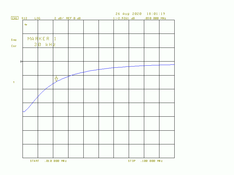
Fig. 1 : The Frequency Response S21 at the lower end
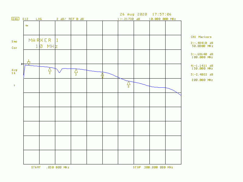
Fig. 2 : The overall Frequency Response
The Insertion Loss in the frequency range of interest is approx. 0.5 dB.
Fig. 1 : The Frequency Response S21 at the lower end
Fig. 2 : The overall Frequency Response
The Insertion Loss in the frequency range of interest is approx. 0.5 dB.
✈ Downloads


✈ Share your thoughts
The webmaster does not read these comments regularely. Urgent questions should be send via email.
Ads or links to completely uncorrelated things will be removed.
|
t1 = 7401 d
t2 = 250 ms |
★ ★ ★ Copyright © 2006 - 2026 by changpuak.ch ★ ★ ★
|
|


