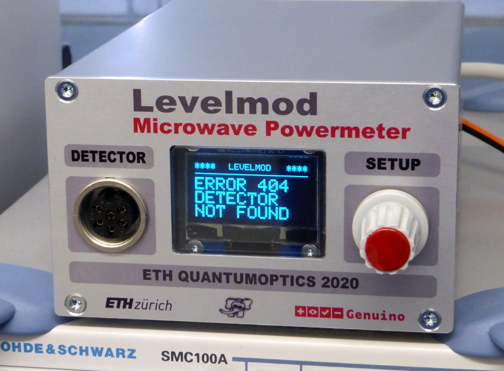
A Microwave Powermeter from DC to Daylight (9 kHz ... 40 GHz)
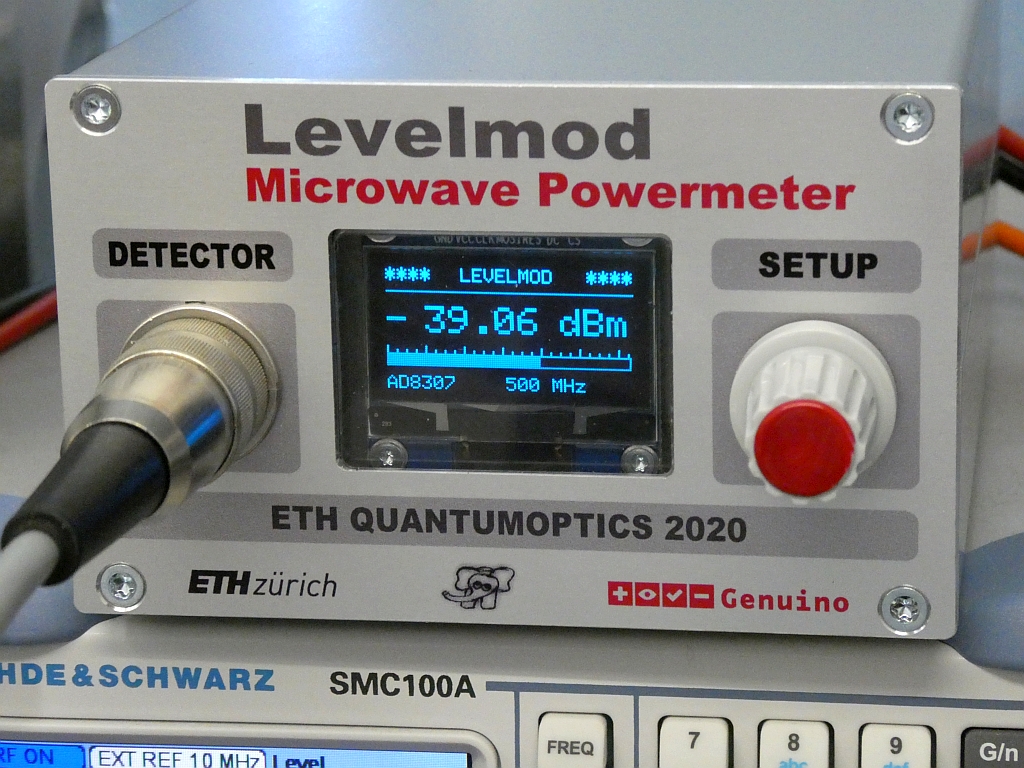
The assembled prototype ... without a Detector :-)
✈ Motivation
In our experiments, it is often necessary to lock something on the amplitude
of a carrier / sideband. Sometimes it is necessary to monitor the presence of
a signal, like the 10 MHz Frequency Standard. In both cases, this - remote controlled -
Powermeter can do the job.
And yes, we don't use 40 GHz, but Linear Technology was
so kind to send free samples. Sharp tongues would say, that I used this "proof
of principle" to build a Radarduino :-)
The date printed on the frontpanel was way too optimistic. This project was released
to public on the first HAM RADIO (Friedrichshafen) after Covid-19, 25.06.2022.
✈ The Design (Display-Unit)
To make things easy, we split the design into a Display-Unit and several Detector Units.
By that, the measurement plane can always be brought close to the source to be measured.
And we have a 'Specialist' for every Measurement-Job. Below is the Block Diagram for the
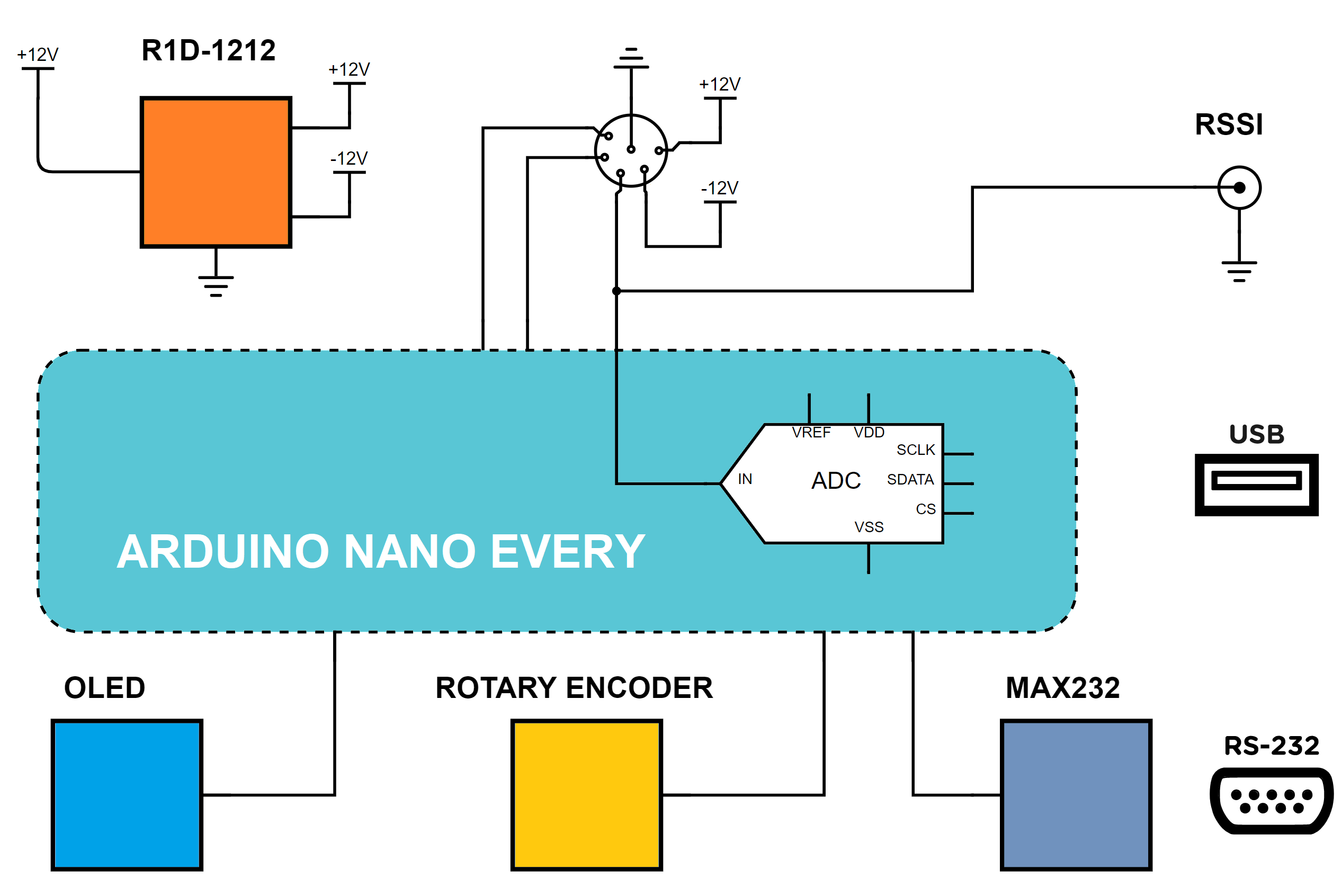
Basestation.
The Basestation mainly consists of the Arduino Nano Every. A DC/DC converter generates
the +12V and the -12V needed for the Opamp on the Detectorboard. This is done by an R1D-1212,
capable of delivering ± 42 mA
In Version 2 we added
a Voltage Regulator to stabilise this +12 V down to +9 V, as the Voltage Regulator
in the Detector (which is used as a Reference for the A/D Converter) seemed to have an
insufficient Line-Regulation.
As there was some space left, we also put the venerable MAX232 with a DSUB connector on the Board.
Even so, the preferred methode is a usb connection.
As the supply voltage is critical (due to the DC/DC converter), the Arduino monitors it.
On the Detectorboard, an Opamp amplifies the raw RSSI signal (which is produced by the
often installed logarithmic amplifier) and makes it available at a BNC
connector on the Basestation. It is also digitized by a LTC2485 (24-Bit ∆Σ ADC). The Pullup - resistors
for the I2C lines are placed on the Detector side. By that, the Base has several ways to see, if
a detctor is connected. First it can measure the raw RSSI level, second it can measure
the voltage level on the SCL and SDA lines.
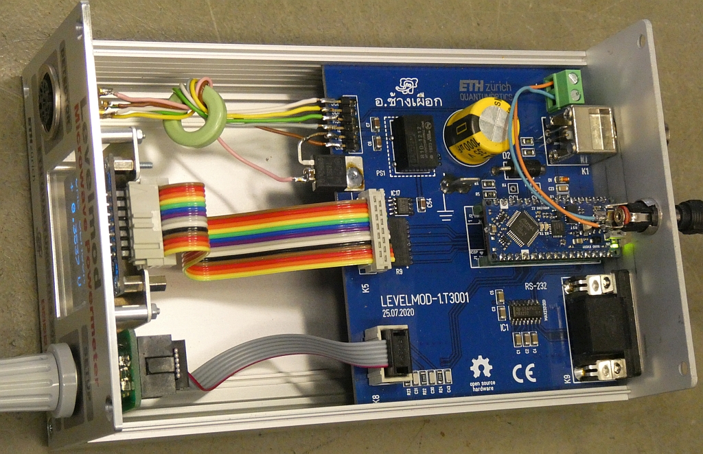
Really not much inside. The magic happens is in the Sensor. And in the Software.
✈ The Connector
We use a KFV 60 (DIN Audio / Video Connector, 6 Contacts, Jack, Panel Mount, Solder, Silver Plated Contacts)
from Lumberg (Farnell Order Code: 1193069) and a SV60 (DIN Audio / Video Connector, IP40, 6 Contacts, Plug,
Cable Mount, Solder, Silver Plated Contacts) from Lumberg (Farnell Order Code: 1321478).
PIN
SIGNAL
REMARK
1
SCL
Pull-up on Detector side
2
SDA
Pull-up on Detector side
3
RSSI
Detector ouput, amplified, Vu = 3
4
- 12 V
unstabilized, max. 40 mA
5
+ 9 V
stabilized, max. 40 mA
6
GND
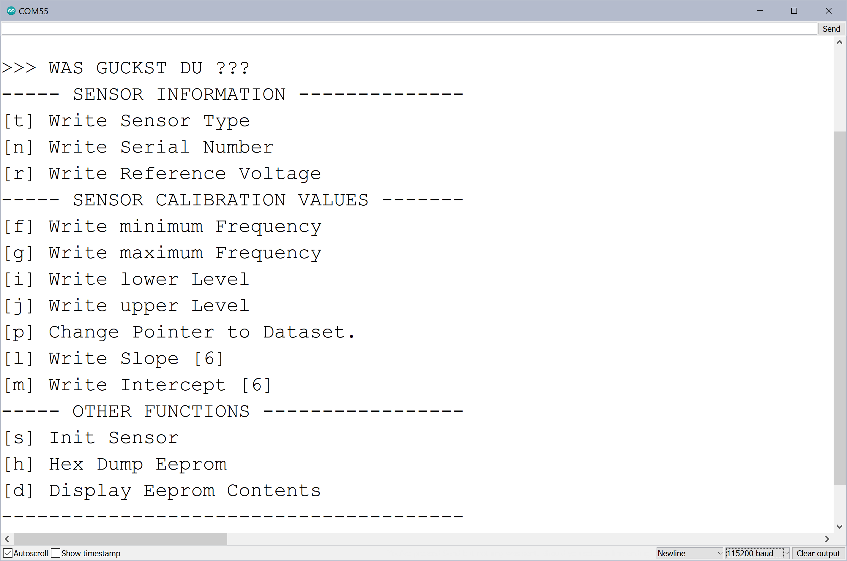
✈ The Calibration
Every Sensor has its own calibration data stored on an onboard Eeprom. This data contains :
ADDRESS
BYTES
CONTENT
0x00
2
Type of Sensor, e.g. 8307, unsigned int
0x02
2
Serialnumber, e.g. 0099, unsigned int
0x04
4
Reference Voltage on Sensor, e.g. 5.024 V, float
0x08
4
Minimum Frequency in MHz, e.g. 1.0, float
0x0C
4
Maximum Frequency in MHz, e.g. 500.0, float
0x10
4
Minimum Level in dBm, e.g. -70.0, float
0x14
4
Maximum Level in dBm, e.g. +10.0, float
0x18
4
Slope @ Frequency[0], float
0x1C
4
Intercept @ Frequency[0], float
0x20
4
Slope @ Frequency[1], float
0x24
4
Intercept @ Frequency[1], float
...
...
...
0x78
4
Slope @ Frequency[12], float
0x7C
4
Intercept @ Frequency[12], float
The intermediate frequencies are calculated by a fixed scheme. (Other schemes mayst be
used as well). From the minimum frequency (0x08) and the maximum frequency (0x0C) the
difference is calculated. The delta-frequency is a fraction of the difference frequency.
We use the following steps :
10% 10% 10% 10% 10% 10% 10% 10% 8% 6% 4% 2%
With Fmin = 1.0 MHz, Fmax = 500.0 MHz, we get a Difference of 499.0 MHz. The calculated Slope
and Intercept values therefore refer to the following frequencies :
F[0]
F[1]
F[2]
F[3]
F[4]
F[5]
F[6]
F[7]
F[8]
F[9]
F[10]
F[11]
F[12]
1
51
101
151
201
251
300
350
400
440
470
490
500
Calibration is done with a trustworthy Synthesiser and a Worksheet (Excel)
or another Calculation Suite of your choice. See the examples in the Detector Section.
For every Frequency, a pair of slope and intersection values is calculated.
These values can then be beamed up to the Eeprom via a serial link.
While Eeprom is empty, the Voltage is displayedCover only opened for Fotomodel :-)
The Calibration of new Sensors is like a 'Kindergeburtstag', using the menu offered :-)
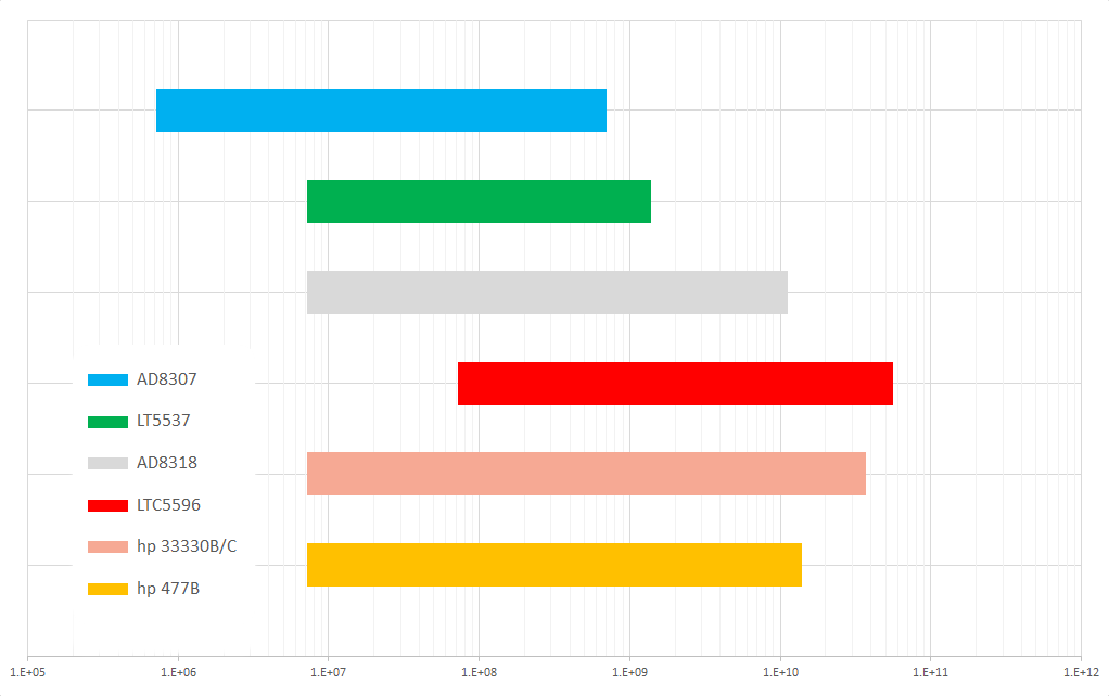
The Frequency Coverage of 'some' Sensors, beeing in the budgetary Range
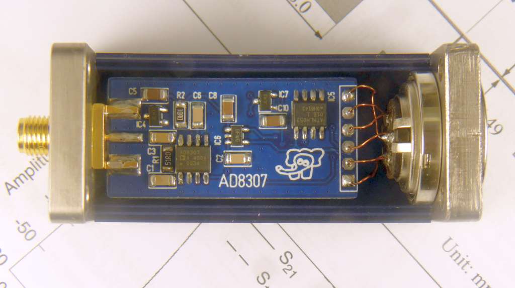
✈ The AD8307 Detector - Type 8307
DETECTOR
FREQUENCY RANGE
LEVEL RANGE
AD 8307
9 kHz ... 500 MHz
-60 dBm ... +10 dBm
This is the workhorse of a lot of RF-Powermeters out there. So we cannot write
much new things and therefore let a picture speak. The case is a Sucobox.
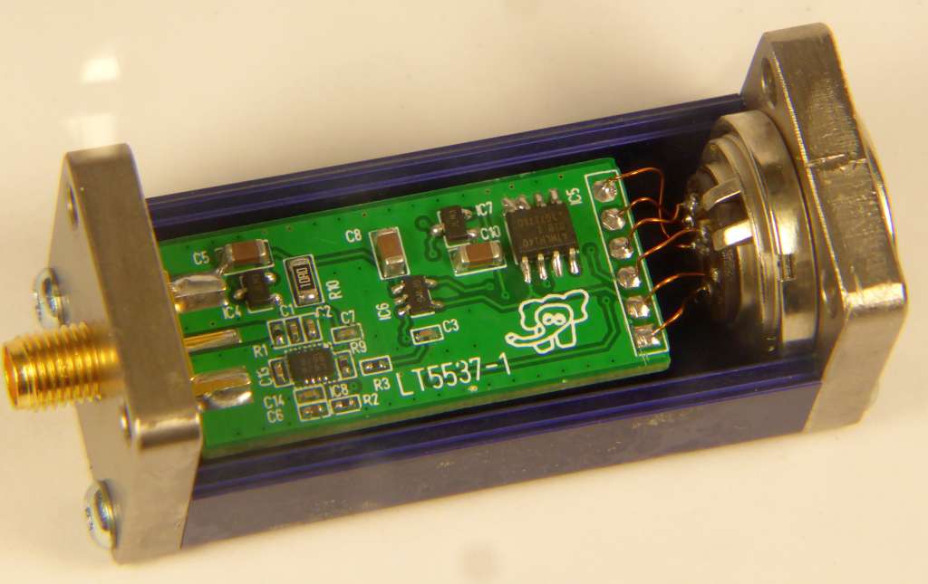
✈ The LT 5537 Detector - Type 5537
DETECTOR
FREQUENCY RANGE
LEVEL RANGE
LT 5537
10 MHz ... 1 GHz
-70 dBm ... 0 dBm
This Detector is almost identical. Just in green. We also replaced the AD8307 by an LT 5537.
The case, again, is a Sucobox. Around the logarithmic Detector are some 0402.
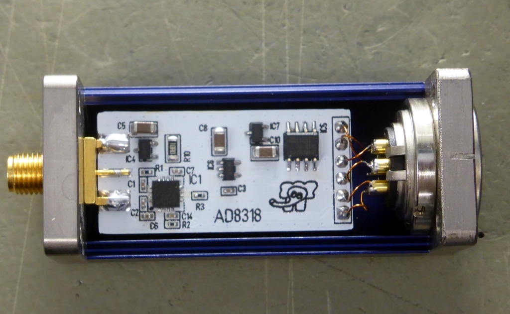
✈ The AD8318 Detector - Type 8318
DETECTOR
FREQUENCY RANGE
LEVEL RANGE
AD 8318
10 MHz ... 8.0 GHz
-60 dBm ... 0 dBm
High accuracy: ±1.0 dB over 55 dB range (f < 5.8 GHz)
Stability over temperature: ±0.5 dB
As we got hands on a bunch of different (broadband) diode detectors, a second website was created,
dealing with them. The Arduino Sketch was expanded to also apply a different handling scheme.
✈ Test Sketch for Arduino/Genuino Nano Every
As the code is long - and the copy & paste procedure causes additional challenges, the file
is provided as a download. Exactly
here.
✈ Remote Control of the Levelmod
COM SETTINGS :
Set up the COM port inside the PC according to the following list.
• Baud rate: 115200
• Parity bit: None
• Data bit: 8
• Stop bit: 1
• Data flow control: None
COMMAND SYNTAX : *IDN?
Description : Returns the Levelmod identification.
Example *IDN?
Returns Levelmod V2.0 by Changpuak.ch (C) 09/2022
*FL?
Description : Returns the LOW Frequency. (Start of CAL Data) in MHz
Example *FL?
Returns 1.0
*FH?
Description : Returns the HIGH Frequency. (End of CAL Data) in MHz
Example *FH?
Returns 500.0
*LL?
Description : Returns the LOWest Level in dBm (Limit)
Example *LL?
Returns -60.0
*LH?
Description : Returns the HIGHest Level in dBm (Limit)
Example *LH?
Returns 0.0
*SP0! , *SP1! , *SP2! , ... , *SP9! , *SPA! , *SPB! , *SPC!
Description : Sets the Pointer to a Frequency for CAL-Data[0...C]
Example *SP9!
Returns 399.0 - this is the corresponding Frequency in MHz
*LVL?
Description : Asks for the corrected Level in dBm
Example *LVL?
Returns -19.99
*VOLT?
Description : Asks for the raw voltage measured
Example *VOLT?
Returns 2.499
*REF?
Description : Asks for the Reference Voltage of the Power Sensor
Example *REF?
Returns 4.999
And that's the view, if a sensor is connected ...
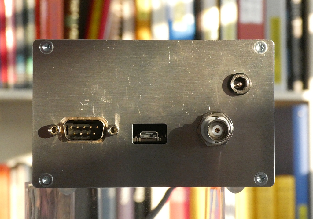
Thanks to Andi and his Team,
the view from behind is also aesthetically pleasing.
✈ Share your thoughts
The webmaster does not read these comments regularely. Urgent questions should be send via email.
Ads or links to completely uncorrelated things will be removed.
 ช้างเผือก