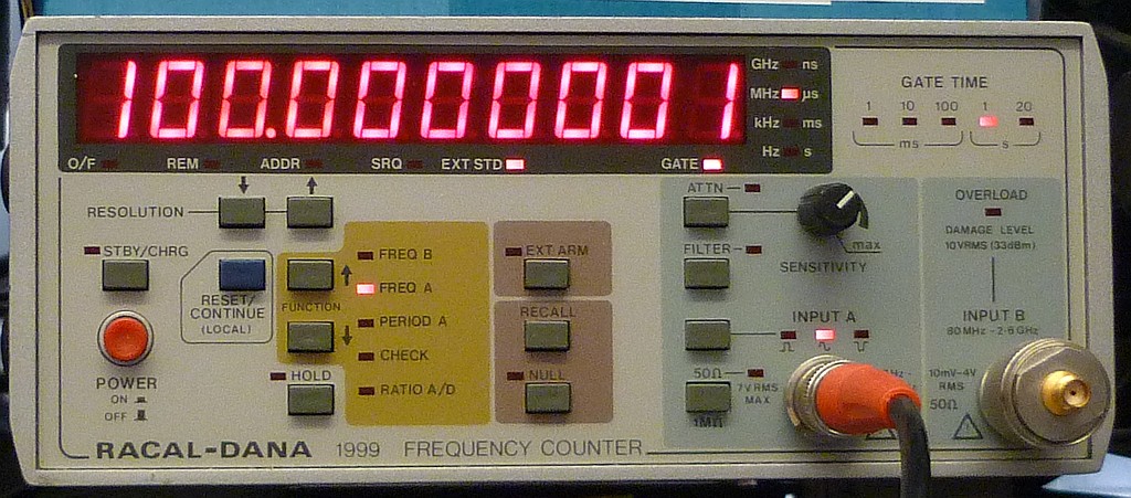
The main actor is an OCXO (AOCJY-10.000MHZ). It has its own voltage regulator. First, because of the large current
when heating up, second to offer maximum stability of the supply. The output is made available at the frontpanel.
With a coaxial connection, you can feed that back in (or use an even better reference). A limiting circuit
and a lowpassfilter (500 Ω not 50 Ω) do some signal beautification. From there, a pll (HMC1031)
takes over and locks a 100 MHz VCXO (ABLNO-V-100.000MHz-T2). Its output is split to four amplifier with the GALI-19+
acting as buffer / isolator. The 100 MHz is available at the frontpanel. A led indicates that the system is locked.
A look inside ... not much there
✈ Downloads
✈ OCXO - Calibration
The OCXO has a stable reference built in, from which (with a 10 kΩ potentiometer) a voltage can be obtained to
be fed back and therefore adjust the frequency by some ppm.
And yes, calibration should be performed after heating up that thing. The potentiometer is accessible
from the rearpanel.
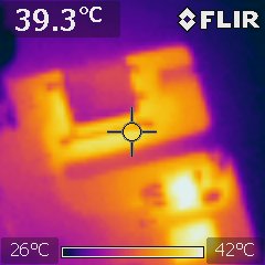
Calibration is done easyThat's where your power goes (OCXO, LD1086)
✈ 10 MHz Input / Output
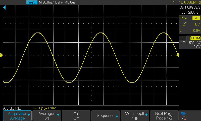
The levels for the 10 MHz Input / Output is defined by the HMC1031. It needs a minimum of 100 mVpp and a maximum
of 3.5 Vpp. This results in a range of -26 dBm up to +19 dBm at the BNC connector on the frontpanel.
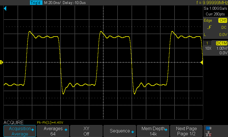
The output is given by the OCXO. We measured a squarewave signal of 3.3 Vpp, ac-coupled, using a high impedance
probe 10:1 (Tektronix TPP0101)
Input +19 dBm, after LowpassOutput of the OCXO, 3.3 Vpp
✈ 100 MHz Output
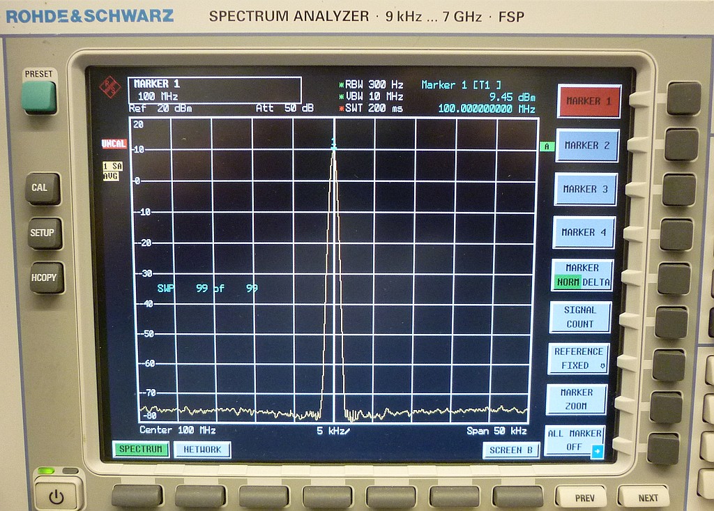
The levels for the 100 MHz Output is approx. +10 dBm.
The Output
✈ Share your thoughts
The webmaster does not read these comments regularely. Urgent questions should be send via email.
Ads or links to completely uncorrelated things will be removed.
 ช้างเผือก