 ช้างเผือก
Categories
Statistics
Since 08.08.2014
Counts only, if "DNT = disabled".
Your IP is 3.143.218.146
ec2-3-143-218-146.us-east-2.
Counts only, if "DNT = disabled".
Your IP is 3.143.218.146
ec2-3-143-218-146.us-east-2.
Info

เราจะทำแบบวิศวกรผู้ยิ่งใหญ่

27. April 2024
Your valuable opinion :
Oscillators.php 16009 Bytes 23-04-2024 11:34:27
CIRCUIT COLLECTION : OSCILLATORS
SECTION 1 .:. AUDIO FREQUENCY
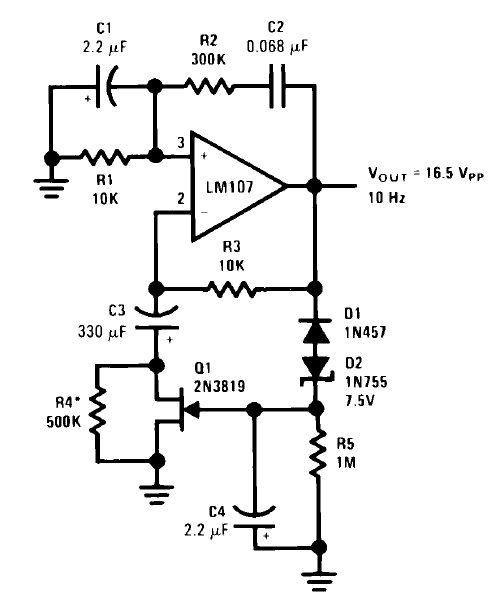
CIRCUIT 1-1 : Wien Bridge Sine Wave Oscillator
Source: National Semiconductor, An Applications Guide for Op Amps
FEATURES :
• high purity sine-wave output
• minimum circuit complexity
FEATURES :
• high purity sine-wave output
• minimum circuit complexity
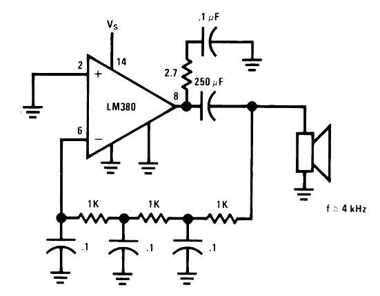
CIRCUIT 1-2 : Phase Shift Oscillator
Source: National Semiconductor, LM 380 Datasheet
FEATURES :
• 3 x RC Phase Shifter
• Freq. approx. 4 kHz
FEATURES :
• 3 x RC Phase Shifter
• Freq. approx. 4 kHz
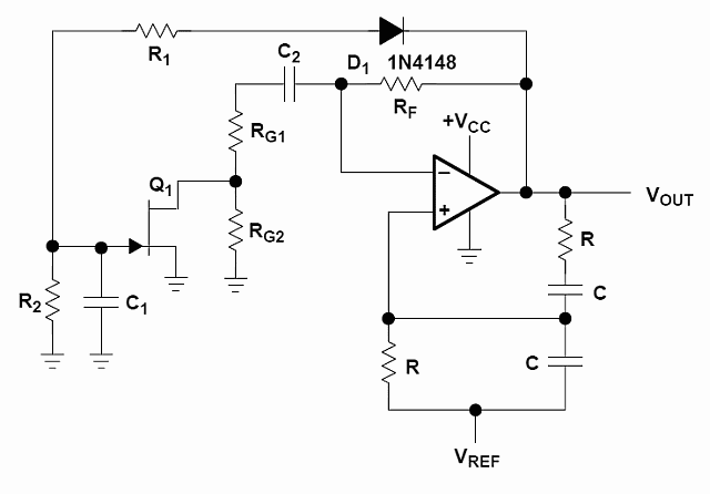
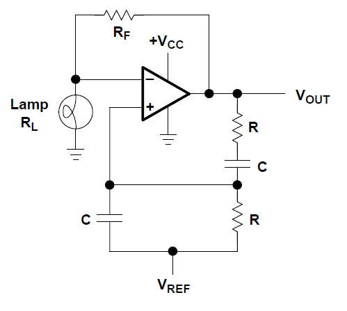
CIRCUIT 1-3 : Wien Bridge Oscillator with AGC
Source: Texas Instruments, Op Amps For Everyone
FEATURES :
• The op amp is configured as an ac amplifier to ease biasing problems
• The diode rectifies the output voltage and applies it to the voltage divider formed by R1, R2
FEATURES :
• The op amp is configured as an ac amplifier to ease biasing problems
• The diode rectifies the output voltage and applies it to the voltage divider formed by R1, R2
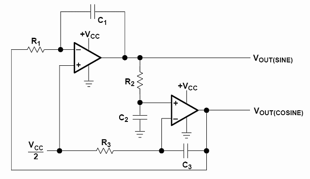
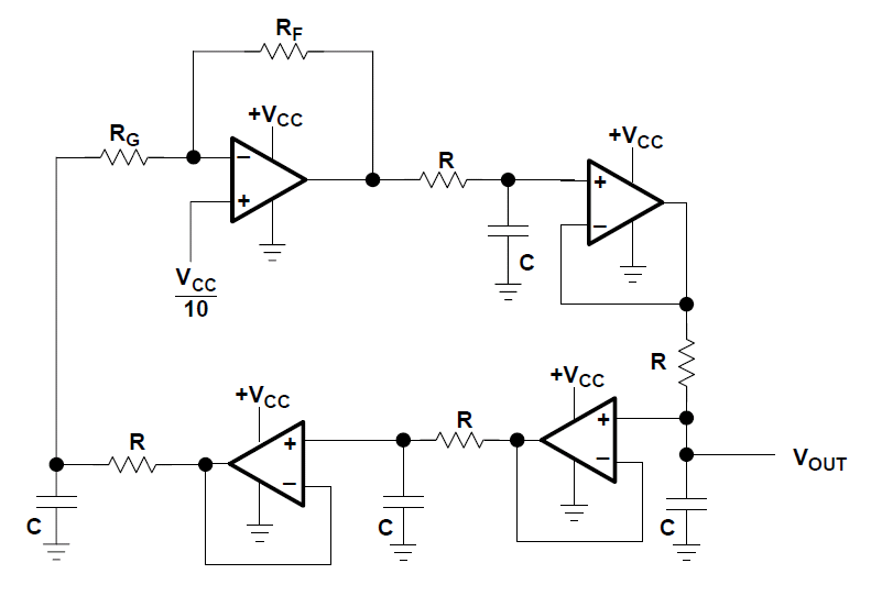
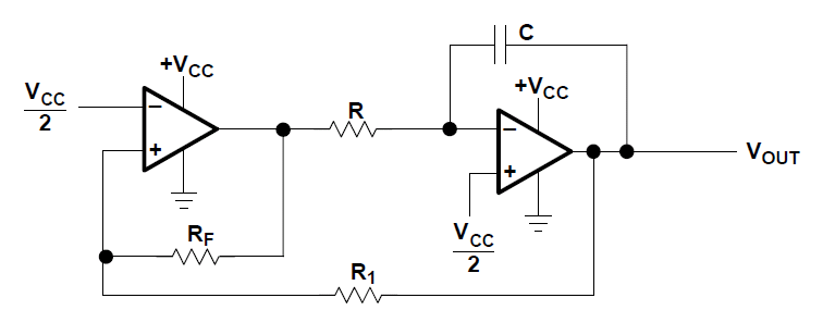
CIRCUIT 1-4 : Quadrature Oscillator
Source: Texas Instruments, Op Amps For Everyone
FEATURES :
• When R1xC1 = R2xC2 = R3xC3, the circuit oscillates at ω = 2πf = 1/RC.
FEATURES :
• When R1xC1 = R2xC2 = R3xC3, the circuit oscillates at ω = 2πf = 1/RC.
CIRCUIT 1-5 : Wien Bridge Oscillator with Nonlinear Feedback
CIRCUIT 1-6 : Classical Phase Shift Oscillator
Source: Texas Instruments, Op Amps For Everyone
FEATURES :
• undistorted sine wave available at the output
FEATURES :
• undistorted sine wave available at the output
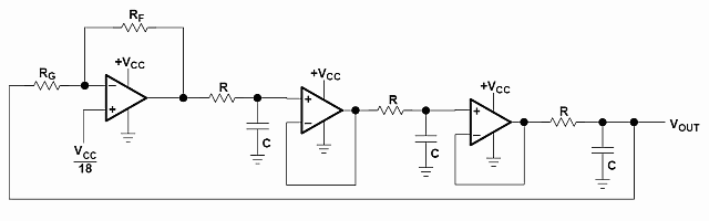
CIRCUIT 1-7 : Buffered Phase Shift Oscillator
Source: Texas Instruments, Op Amps For Everyone
FEATURES :
• undistorted sine wave available at the output
FEATURES :
• undistorted sine wave available at the output
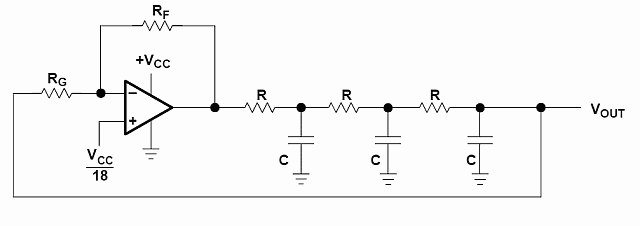
CIRCUIT 1-8 : Bubba Oscillator
Source: Texas Instruments, Op Amps For Everyone
FEATURES :
• The Bubba oscillator is another phase shift oscillator
• Four RC sections require –45° phase shift per section
• Very low distortion sine waves can be obtained
FEATURES :
• The Bubba oscillator is another phase shift oscillator
• Four RC sections require –45° phase shift per section
• Very low distortion sine waves can be obtained
CIRCUIT 1-9 : Triangle Oscillator
Source: Texas Instruments, Op Amps For Everyone
FEATURES :
• The triangle oscillator produces triangle waves and square waves
FEATURES :
• The triangle oscillator produces triangle waves and square waves
SECTION 2 .:. CRYSTAL OSCILLATORS
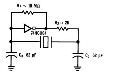
CIRCUIT 2-1 : Typical Gate Oscillator
Source: Fairchild Semiconductor, HCMOS Crystal Oscillators
HINTS :
• Choose R2 to have approx. XC at Freq. of Operation
• Use equal capacitor values for Ca and Cb
HINTS :
• Choose R2 to have approx. XC at Freq. of Operation
• Use equal capacitor values for Ca and Cb
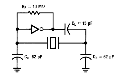
CIRCUIT 2-2 : Gate Oscillator for Higher Frequencies
Source: Fairchild Semiconductor, HCMOS Crystal Oscillators
HINTS :
• If the Freq. is larger than 4 MHz, the additional Phase-Shift is done by the delay of the Gate.
• The value of CL is approx. 1/ωC where ω=2pf, but not less than about 20 pF.
HINTS :
• If the Freq. is larger than 4 MHz, the additional Phase-Shift is done by the delay of the Gate.
• The value of CL is approx. 1/ωC where ω=2pf, but not less than about 20 pF.
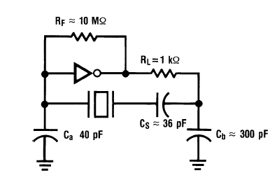
CIRCUIT 2-3 : Gate oscillator with improved stability
Source: Fairchild Semiconductor, HCMOS Crystal Oscillators
HINTS :
• A small C in series with the xtal acts as the xtal load and isolates the xtal from the rest.
• Ca and Cb are made large to swamp out the effects of Temp. / Supply Voltage change.
HINTS :
• A small C in series with the xtal acts as the xtal load and isolates the xtal from the rest.
• Ca and Cb are made large to swamp out the effects of Temp. / Supply Voltage change.
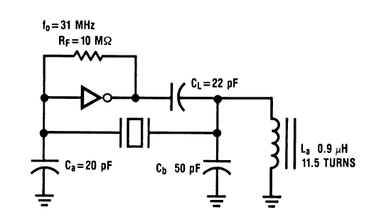
CIRCUIT 2-4 : Parallel Mode Overtone Circuit
Source: Fairchild Semiconductor, HCMOS Crystal Oscillators
HINTS :
• This circuit operates in the parallel mode just as the Pierce oscillator above.
• The resonant circuit LA-CB is an effective short at the fundamental frequency
• It is tuned somewhat below the deferred crystal overtone frequency.
• CL is chosen to suppress operation in the fundamental mode.
• LA may be tuned to produce maximum output.
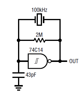
CIRCUIT 2-5 : 74C14 XTAL Oscillator 100 kHz
Source: Linear Technology, Circuit Techniques for Clock Sources
HINTS :
• Please read the Application Note.
HINTS :
• Please read the Application Note.
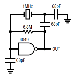
CIRCUIT 2-6 : 4049 XTAL Oscillator 1 MHz
Source: Linear Technology, Circuit Techniques for Clock Sources
HINTS :
• Please read the Application Note.
HINTS :
• Please read the Application Note.
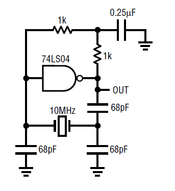
CIRCUIT 2-7 : 74LS04 XTAL Oscillator 10 MHz
Source: Linear Technology, Circuit Techniques for Clock Sources
HINTS :
• Please read the Application Note.
HINTS :
• Please read the Application Note.
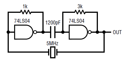
CIRCUIT 2-8 : 74LS04 XTAL Oscillator 5 MHz
Source: Linear Technology, Circuit Techniques for Clock Sources
HINTS :
• Please read the Application Note.
HINTS :
• Please read the Application Note.
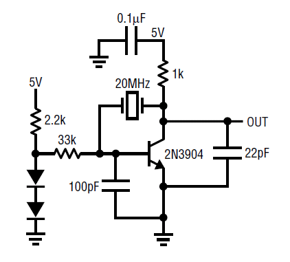
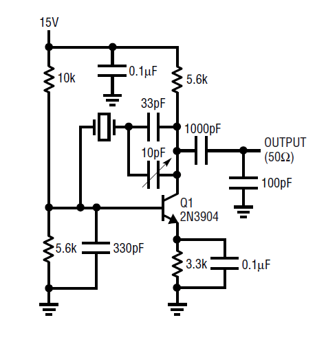
CIRCUIT 2-9 : 2N3904 XTAL Oscillator 20 MHz
Source: Linear Technology, Circuit Techniques for Clock Sources
HINTS :
• Please read the Application Note.
HINTS :
• Please read the Application Note.
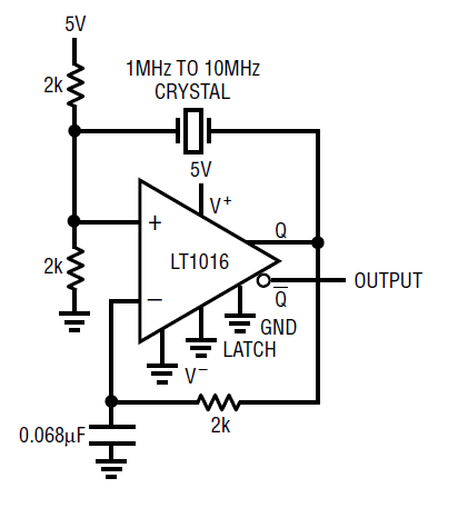
CIRCUIT 2-10 : LT1016 XTAL Oscillator 1...10 MHz
Source: Linear Technology, Circuit Techniques for Clock Sources
HINTS :
• Please read the Application Note.
HINTS :
• Please read the Application Note.
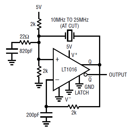
CIRCUIT 2-11 : LT1016 XTAL Oscillator 10...25 MHz
Source: Linear Technology, Circuit Techniques for Clock Sources
HINTS :
• Please read the Application Note.
HINTS :
• Please read the Application Note.
CIRCUIT 2-12 : 2N3904 XTAL Oscillator
Source: Linear Technology, Circuit Techniques for Clock Sources
HINTS :
• Please read the Application Note.
HINTS :
• Please read the Application Note.
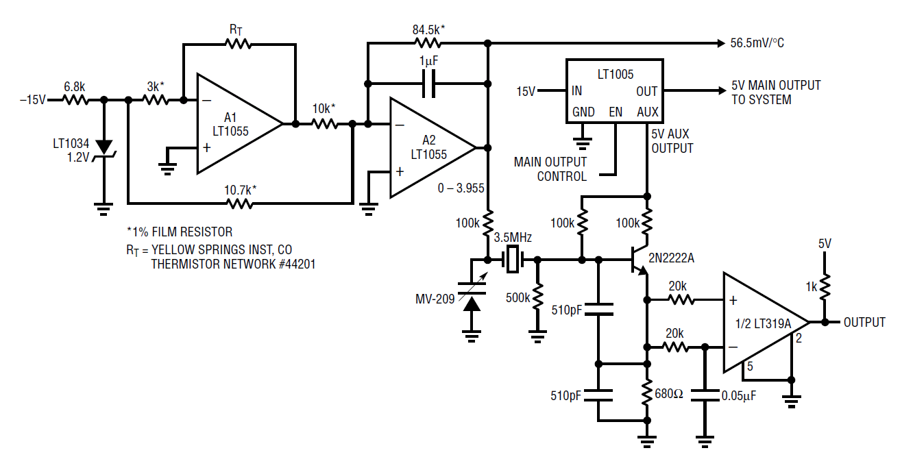
CIRCUIT 2-13 : Temperature Compensated Crystal Oscillator
Source: Linear Technology, Circuit Techniques for Clock Sources
HINTS :
• Please read the Application Note.
HINTS :
• Please read the Application Note.
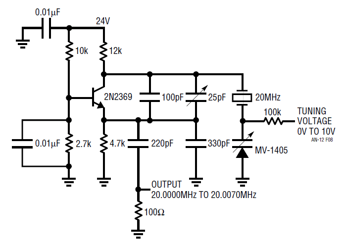
CIRCUIT 2-14 : Voltage Controlled Crystal Oscillator (VCXO)
Source: Linear Technology, Circuit Techniques for Clock Sources
HINTS :
• Please read the Application Note.
HINTS :
• Please read the Application Note.
✈ Share your thoughts
The webmaster does not read these comments regularely. Urgent questions should be send via email.
Ads or links to completely uncorrelated things will be removed.
Your Browser says that you allow tracking. Mayst we suggest that you check that DNT thing ?
|
t1 = 6498 d
t2 = 291 ms |
★ ★ ★ Copyright © 2006 - 2024 by changpuak.ch ★ ★ ★
|

|