 ช้างเผือก
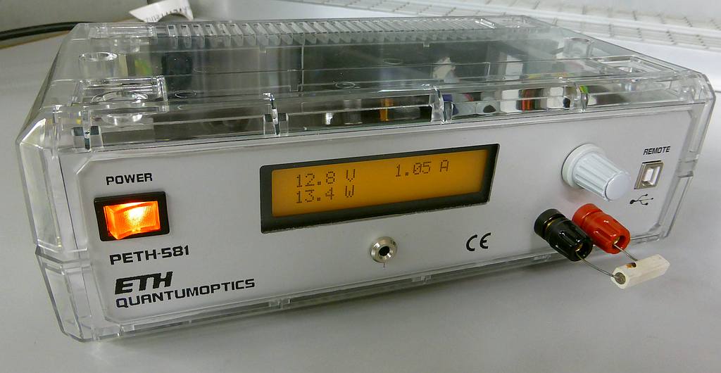
Categories
Statistics
Since 08.08.2014
Counts only, if "DNT = disabled".
Your IP is 3.144.96.159
ec2-3-144-96-159.us-east-2.c
Counts only, if "DNT = disabled".
Your IP is 3.144.96.159
ec2-3-144-96-159.us-east-2.c
Info

เราจะทำแบบวิศวกรผู้ยิ่งใหญ่

28. April 2024
Your valuable opinion :
PETH-581.php 7980 Bytes 12-02-2018 11:23:31
PETH-581 • Power Supply with Atmega 328
A Buck Converter with a linear Afterburner
This project describes a power supply, fully controlled by a microprofessor. It is a cascaded approach,
a step-down converter (LT1074) generates an intermediate voltage which is then linear regulated by a TIP-3055.
So it is economical and low noise. As it is digital, output voltage
ranges from 0 to 25.5 V and 0 to 2.55 A. You guess right. Resolution is 0.1 V and 0.01 A.
The Power Supply in action - yes, the 5 W resistor had to suffer :-)
✈ Circuit
The circuit mainly consists of three building blocks. First a rectifier with storage capacitors delivers an unregulated dc voltage to the step down converter (LT1074).
The feedback for this circuit is not generated by the voltage of its output, but by a current dependant on the difference of the voltage over the linear regulator.
This difference causes a current through T3, R5, R6 and is monitored by IC1 as a voltage across R5 (Pin 1, FB).
The intermediate voltage is always ~ 5 V above the desired output voltage to allow some headroom for the linear regulator. (Can be lowered even more)
This intermediate voltage is then input to the linear regulator around the TIP3055. It's driver is a BD243C who is trying to increase the output voltage due to its base resistor connected to the (higher) unregulated dc voltage. A digital potentiometer (MCP41010-I/P, R14 and R15) defines the target voltage as well as the maximum current. Should the output voltage reach its target value, the regulation (IC9c) starts to 'steal' base current from the driver (T2). The same happens, if the output current reaches its maximum value (IC9b). The current is monitored with a level shifting circuit around the 0.1 Ω sensing resistor (R9,R13,T1,R12,IC9d). As the opamp always tries to maintain zero volt across its inputs, the current through the 100 Ω resistor is therefore, that the voltage drops across it and the sensing resistors are equal. This current causes a voltage drop across the 1 kΩ resistor which is proportinal to the output current. (and ground referenced).
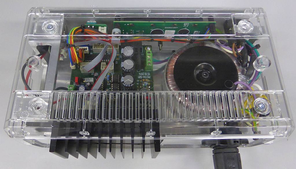
The controlling is handled by an ATmega328 (IC3). A usb bridge as well as a rotary encoder are used as interface. A 2x20 lcd displays voltage, current and power, as well as a small menue to set these values. The device can operate in cv (constant voltage) or cc (constant current) mode.
This intermediate voltage is then input to the linear regulator around the TIP3055. It's driver is a BD243C who is trying to increase the output voltage due to its base resistor connected to the (higher) unregulated dc voltage. A digital potentiometer (MCP41010-I/P, R14 and R15) defines the target voltage as well as the maximum current. Should the output voltage reach its target value, the regulation (IC9c) starts to 'steal' base current from the driver (T2). The same happens, if the output current reaches its maximum value (IC9b). The current is monitored with a level shifting circuit around the 0.1 Ω sensing resistor (R9,R13,T1,R12,IC9d). As the opamp always tries to maintain zero volt across its inputs, the current through the 100 Ω resistor is therefore, that the voltage drops across it and the sensing resistors are equal. This current causes a voltage drop across the 1 kΩ resistor which is proportinal to the output current. (and ground referenced).
The controlling is handled by an ATmega328 (IC3). A usb bridge as well as a rotary encoder are used as interface. A 2x20 lcd displays voltage, current and power, as well as a small menue to set these values. The device can operate in cv (constant voltage) or cc (constant current) mode.
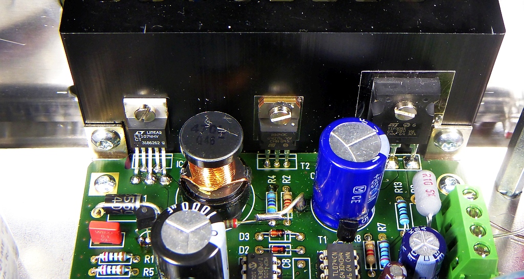
Buck Converter (LT1074) left, linear Regulator (TIP3055) right
✈ Downloads


✈ Notes
The version presented here is V3.0 which uses the internal r-c oscillator of the ATmega. This is not the smartest choice when doing
uart-business. We do recommend an Arduino Micro to handle the "remote" stuff. The Sourcecode went up in smoke with one
of my last notebooks. It was written with CVAVR for which I don't have a license anymore.
✈ Share your thoughts
The webmaster does not read these comments regularely. Urgent questions should be send via email.
Ads or links to completely uncorrelated things will be removed.
Your Browser says that you allow tracking. Mayst we suggest that you check that DNT thing ?
|
t1 = 6499 d
t2 = 181 ms |
★ ★ ★ Copyright © 2006 - 2024 by changpuak.ch ★ ★ ★
|

|