 ช้างเผือก
Categories
Statistics
Since 08.08.2014
Counts only, if "DNT = disabled".
Your IP is 3.144.115.16
ec2-3-144-115-16.us-east-2.c
Counts only, if "DNT = disabled".
Your IP is 3.144.115.16
ec2-3-144-115-16.us-east-2.c
Info

เราจะทำแบบวิศวกรผู้ยิ่งใหญ่

11. May 2024
Links (Drehst du Bildschirm :-)

Application Notes

Your valuable opinion :
PLL_Seminar_1.php 12994 Bytes 12-02-2018 11:22:33
Mini PLL Seminar #1 - Theory
Introduction
A PLL (Phase Locked Loop) may be found in almost every electronic device. In a television, it makes shure, that green is always green - and that the head
of the actress is at the top of the screen and the feet at the bottom.
In general, it is a circuit which causes a system to track
(synchronise) with an other system. Usually a free running oscillator (VCO) is locked in frequency and phase to a very stable Reference
(XCO, OCXO, Rubidium Standard, Caesium Standard, ...).
To achieve this, a PLL consists of the following parts (minimum) :
• A Phase Detector (PD)
• A Loop Filter (LF)
• A Voltage Controlled Oscillator (VCO)
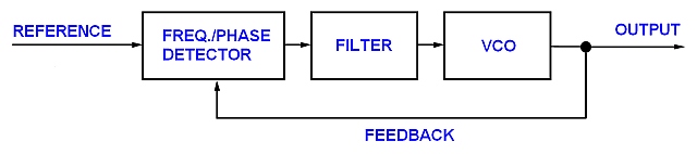
Let's have a look at those three functional blocks.
The VCO
The VCO produces a frequency which is proportional to the Tuning Voltage.
We can therefore note:
FREQ(VCO) = FREQ(VCO,0) + K0 * VTUNE
where K0 is the VCO Gain in s-1 * V-1
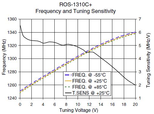
Frequency as a Function of Tuning Voltage, Drawing courtesy of Mini Circuits ™
The Frequency / Phase Detector (PD)
The Phase Detector (also referred to as Phase Comparator) compares the Phase of the Output Signal with the Phase of the Reference Signal
and develops an output signal which is approximately proportional to the Phase Error (at least within a limited range).
We can therefore note:
U(t) = Kd * PhaseError
Here Kd represents the Gain of the Phase Detector. (Unit: Volt/rad).
The Output of the Phase Detector is a DC Voltage and a superimposed AC-Component.
(As with a Mixer, you'll get the Sum and the Difference)
Depending on the Phase Detector, the PLL has a different behaviour.
Phase Detector | Pull-in-Range | Hold-Range |
DIGITAL:XOR | tba | tba |
DIGITAL:- | tba | tba |
The Loop Filter
The Loop Filter has the job to supress the unwanted AC-Component produced by the PD.
As we are interested in the DC Voltage, the Loop Filter always has a Lowpass Character.
Let's see, how this System works.
If we switch on this system, the VCO will start at its Minimum Frequency, because the Loop-Filter Capacitors
are discharched. The Frequency/Phase Detector will produce Pulses at its Output which are integrated by
the Loop Filter. The Frequency of the VCO will increase (as the Tuning Voltage will increase).
As the frequencies are almost equal, the Phase is aligned.
Below is a Visualisation to see how the Tuning Voltage (=lowpass filtered Output of the Frequency/Phase Detector)
changes depending of the Phase Offset (=Phase Error). Change the Phase Error to see by yourself ...
INCREASE PHASE ERROR : DECREASE PHASE ERROR :
The Visualisation uses Google's ™ Code flot
The Phase Error is evaluated with an EXOR Phase Detector and an ideal Integrator (Lowpass).
That's nice, but why should I use a lot of circuits to synchronise two frequencies ?
I can use the Reference directly !
Well, it may be the case, that the Reference is not always present (Colour Carrier in PAL Television) or you
may want to synthesize Frequencies and therefore have an additional Divide-by-N Counter in the Feedback Loop.
Expanding the System - creating a Frequency Synthesizer
If we add a Divide-by-N Counter in the Feedback Loop, we are able to synthesize Frequencies which have the Frequency of N * Reference.
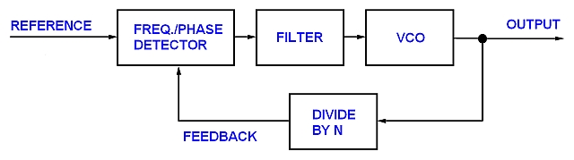
This is useful if you want to build a Radio (Receiver) or a Frequency Synthesizer. For airband (108 - 137 MHz) the channel-spacing is 8.33 kHz.
You would therefore choose the Reference to be 8.33 kHz and then alter the Divide-by-N Counter to reach the desired Channel.
Continue with Part #2 - Practise click here
✈ Share your thoughts
The webmaster does not read these comments regularely. Urgent questions should be send via email.
Ads or links to completely uncorrelated things will be removed.
Your Browser says that you allow tracking. Mayst we suggest that you check that DNT thing ?
|
t1 = 6512 d
t2 = 181 ms |
★ ★ ★ Copyright © 2006 - 2024 by changpuak.ch ★ ★ ★
|

|