 ช้างเผือก
Categories
Statistics
Since 08.08.2014
Counts only, if "DNT = disabled".
Your IP is 3.144.143.31
ec2-3-144-143-31.us-east-2.c
Counts only, if "DNT = disabled".
Your IP is 3.144.143.31
ec2-3-144-143-31.us-east-2.c
Info

เราจะทำแบบวิศวกรผู้ยิ่งใหญ่

29. April 2024
Your valuable opinion :
Quartz_Crystal_Filter_Designer_1.php 11152 Bytes 12-02-2018 11:22:31
Quartz Crystal Filter Design
Equivalent Circuit Determination of Quartz Crystals
Before we may design a crystal filter it is necessary to know the crystal's data.
Unfortunately this information is not in the datasheet - or we have no datasheet
because the crystals were bought on a market some decades ago ...
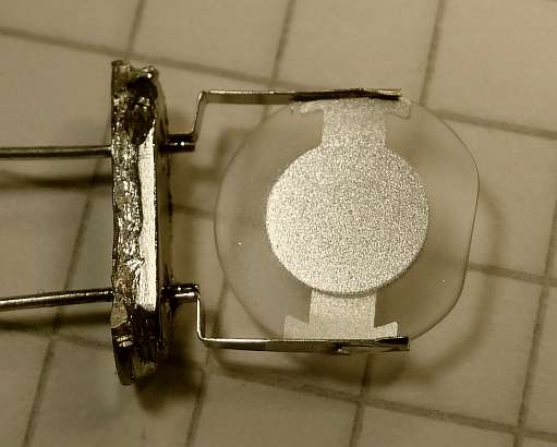
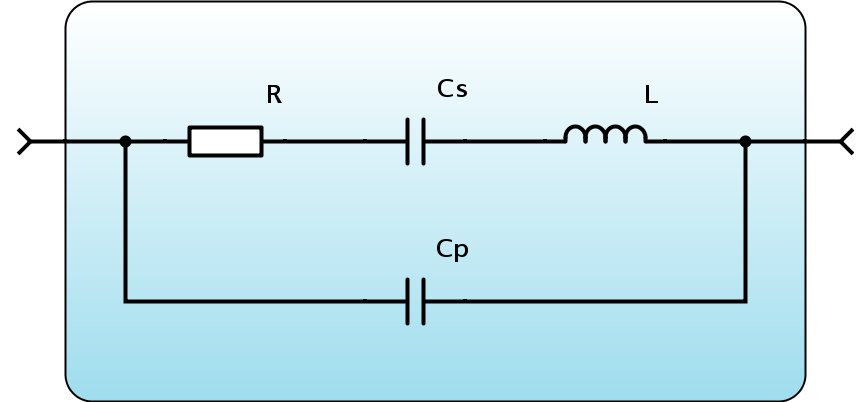
A quartz crystal and its equivalent circuit
As you may have guessed from the equivalent circuit above, a quartz crystal has a series resonance (Cs and L) as well as a
parallel resonance. This may be observed very well, when doing a frequency sweep, using the quartz as a series element.
In order to determine these four values (R, Cs, L, Cp) one measurement is not enough. We use a small testfix for the frequency
sweep. Building such a thing allows for stable electronic and mechanical conditions, leading to reliable and reproduceable results.
Those four values may be obtained by four measurements :
• Holder Capacitance : Cp
• Series resonance frequency : fs
• Parallel resonance frequency : fp
• The dynamic Losses : R
Those four values may be obtained by four measurements :
• Holder Capacitance : Cp
• Series resonance frequency : fs
• Parallel resonance frequency : fp
• The dynamic Losses : R
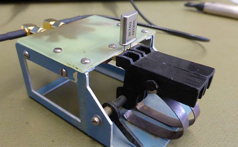
Measurement Adapter in Action, Details about this test fixture
Measure Cp
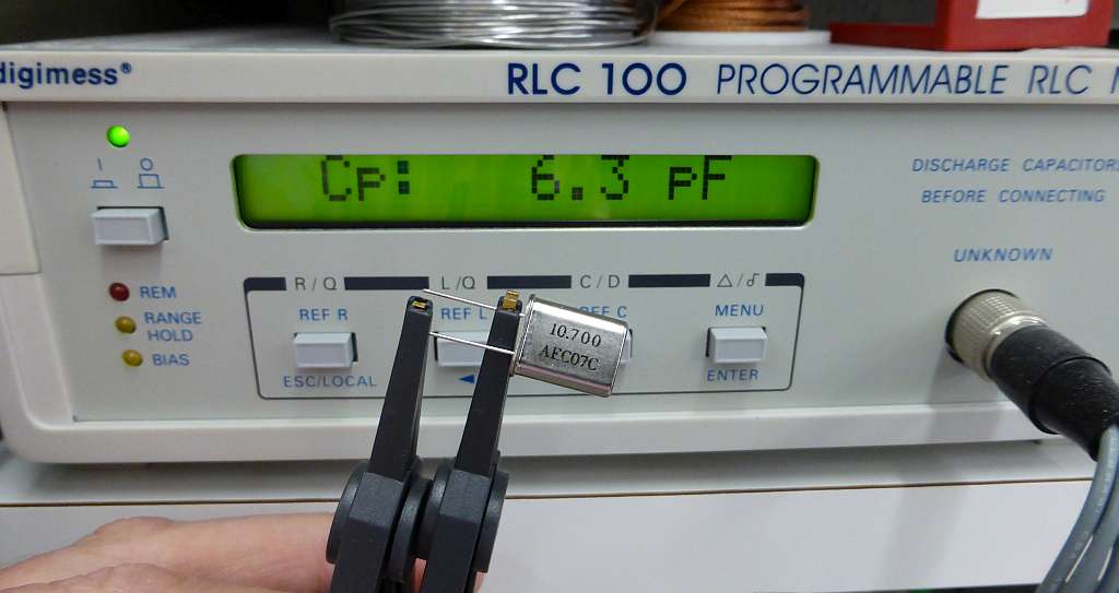 The easiest way to get this value is the use of a RLC-Meter. This has the ad- vantage, that no calibration is neces- sary. (Except zero).
The easiest way to get this value is the use of a RLC-Meter. This has the ad- vantage, that no calibration is neces- sary. (Except zero).
Measure fs and fp
The Series / Paralle resonance frequency may be measured by a lot of setups. A vector network analyser is of course the luxury version, but you
may as well use a generator and a scope, a spectrum analyser with a generator or any linear combination thereof. The quartz crystal is connected
in series between the source and the load. We are intersted in the maximum amplitude (fs, where XL = XCs) and the minimum (fp, where XL and XCs,
XCp form a block).
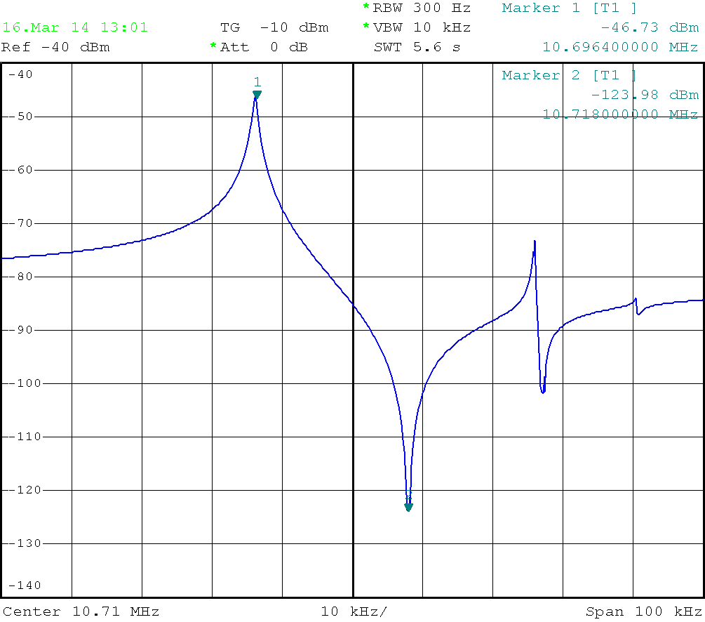
Measured Amplitude Response of a Quartz Crystal in the test fixture
Measure Insertion Loss at fs
This measurement targets the internal "Resistor". We measure exactly at the series resonance frequency, because there,
XL and XCs sum up to zero. So what is left, is a (resistive) voltage divider, consisting of your source, the R from the quartz
and the load. Whereas source and load are mostly 50 Ω. Please keep in mind to calibrate or to measure the difference (shorted /
quartz inserted).
PROCEED HERE TO LADDER FILTER CALCULATOR
The Mathematics behind
Series resonance frequency : `fs = 1 / ( 2 pi sqrt(L Cs) ` (1)
Parallel resonance frequency : ` fp = fs sqrt(1 + (Cs)/(Cp) ) ` (2)
Quality factor at fs : ` Q = 1/R sqrt((Ls)/(Cs)) = ( 2 pi fs Ls) / R ` (3)
R as a function of Insertion Loss : ` Rs = 2 Zo (10^(a/20)-1) ` (4)
Equation (2) may be rewritten as : ` Cs = Cp ( (fp^2) / (fs^2) - 1) `
And from Equation (1) we get : ` Ls = 1 / ( 4 pi^2 fs^2 Cs ) `
Credits :
The Visualisation uses https://www.mathjax.org/
✈ Share your thoughts
The webmaster does not read these comments regularely. Urgent questions should be send via email.
Ads or links to completely uncorrelated things will be removed.
Your Browser says that you allow tracking. Mayst we suggest that you check that DNT thing ?
|
t1 = 6500 d
t2 = 339 ms |
★ ★ ★ Copyright © 2006 - 2024 by changpuak.ch ★ ★ ★
|

|