 ช้างเผือก

Categories
Statistics
Since 08.08.2014
Counts only, if "DNT = disabled".
Your IP is 18.216.230.107
ec2-18-216-230-107.us-east-2
Counts only, if "DNT = disabled".
Your IP is 18.216.230.107
ec2-18-216-230-107.us-east-2
Info

เราจะทำแบบวิศวกรผู้ยิ่งใหญ่

28. April 2024
further reading
Your valuable opinion :
Curve_Tracer.php 7393 Bytes 23-04-2024 09:20:09
Curve Tracer Project
Insignificant BOM but surprising skills !
A Curve Tracer is a Device which will show the Voltage / Current dependency
of an electronic part. It is therefore suiteable to discover characteristics of
electronic parts - and to quickly check if they are o.k. - or if the smoke left aleady.
This Project is useful for educational reasons, as it is simple but clever.
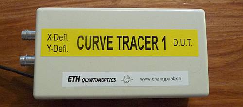
Fig.1 .:. Homebrew Curve Tracer - a very handy Tool !
All we need is an Oscilloscope with an x and an y input. (This feature is available in almost every Oscilloscope.) The horizontal axis represents the Voltage (x) whilst the vertical axis (y) represents the Current.
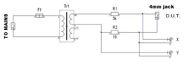
Fig.2 .:. Schematics
The minimum Configuration uses only three parts :
• A Transformer
• A Current Limit Resistor (R1)
• A Current Sense Resistor (R2)
(There is a 330pF Capacitor to reduce noise, parallel R2)
We used a Transformer with 15V which will deliver 30Vp or 60Vpp. In order to
limit the current to 10mA, R1 was chosen to be 3kΩ. R2 was chosen to be 10Ω.
A more luxurious Version may use a Switch to select different maximum Currents.
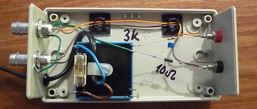
Fig.3 .:. Built 'on the fly'
With this configuration, the following curves have been measured :
(Set the Y-Channel to 'inverting')
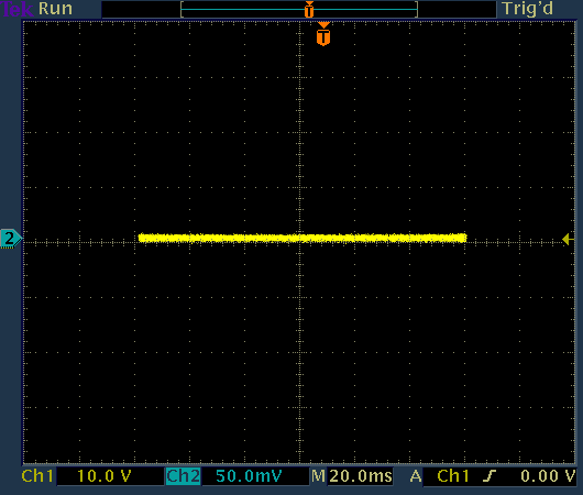
Fig.4 .:. No D.U.T. - High-Z
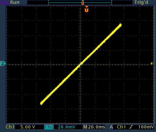
Fig.5 .:. A Resistor of 2.5 kΩ - 5V/Div : 2mA/Div
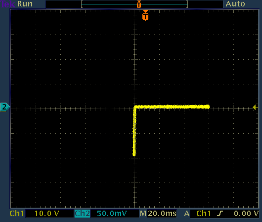
Fig.6 .:. 1N4007 Diode
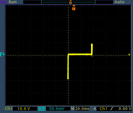
Fig.7 .:. A Zener Diode of 18 V
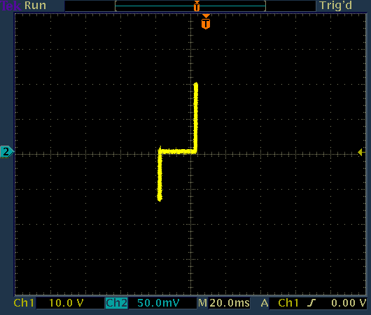
Fig.8 .:. A Zener Diode of 9.1 V - the other way
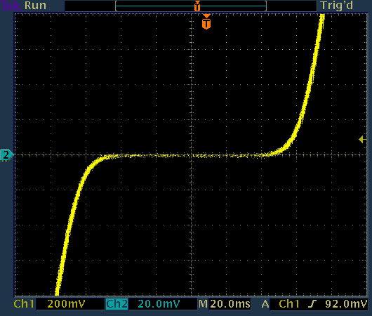
Fig.9 .:. Two Diodes 1N4007 - antiparallel
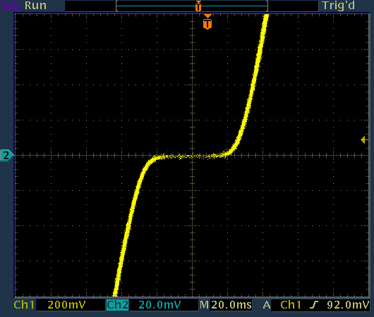
Fig.10 .:. Two Diodes 1N5711 (Schottky) - antiparallel
Fig.11 .:. Two Diodes 5082-2835 (Schottky) - antiparallel
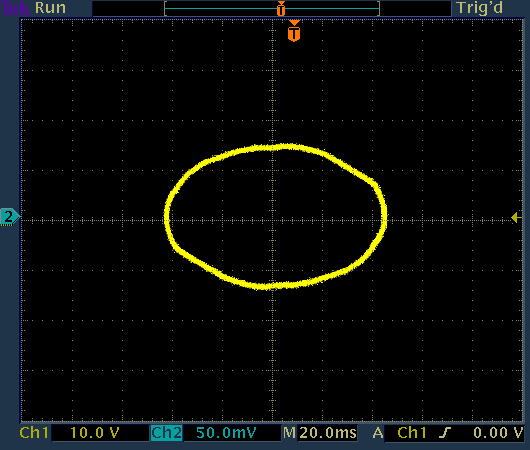
Fig.12 .:. A Capacitor - C = 1 µF
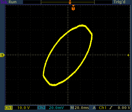
Fig.13 .:. A Resistor 2.5 kΩ in series with a Capacitor C = 1 µF
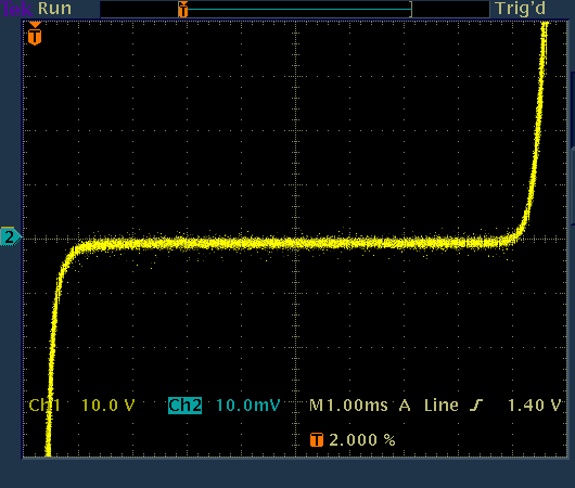
Fig.14 .:. A Varistor, EPCOS S05K25
This Section will add Gate / Base Drive in order to examine Transistors.
Click here to go to the advanced Curve Tracer Website.
All we need is an Oscilloscope with an x and an y input. (This feature is available in almost every Oscilloscope.) The horizontal axis represents the Voltage (x) whilst the vertical axis (y) represents the Current.
Fig.2 .:. Schematics
The minimum Configuration uses only three parts :
• A Transformer
• A Current Limit Resistor (R1)
• A Current Sense Resistor (R2)
(There is a 330pF Capacitor to reduce noise, parallel R2)
We used a Transformer with 15V which will deliver 30Vp or 60Vpp. In order to
limit the current to 10mA, R1 was chosen to be 3kΩ. R2 was chosen to be 10Ω.
A more luxurious Version may use a Switch to select different maximum Currents.
Fig.3 .:. Built 'on the fly'
With this configuration, the following curves have been measured :
(Set the Y-Channel to 'inverting')
Fig.4 .:. No D.U.T. - High-Z
Fig.5 .:. A Resistor of 2.5 kΩ - 5V/Div : 2mA/Div
Fig.6 .:. 1N4007 Diode
Fig.7 .:. A Zener Diode of 18 V
Fig.8 .:. A Zener Diode of 9.1 V - the other way
Fig.9 .:. Two Diodes 1N4007 - antiparallel
Fig.10 .:. Two Diodes 1N5711 (Schottky) - antiparallel
Fig.11 .:. Two Diodes 5082-2835 (Schottky) - antiparallel
Fig.12 .:. A Capacitor - C = 1 µF
Fig.13 .:. A Resistor 2.5 kΩ in series with a Capacitor C = 1 µF
Fig.14 .:. A Varistor, EPCOS S05K25
Curve Tracer Project .:. Part 2
This Section will add Gate / Base Drive in order to examine Transistors.
Click here to go to the advanced Curve Tracer Website.
✈ Share your thoughts
The webmaster does not read these comments regularely. Urgent questions should be send via email.
Ads or links to completely uncorrelated things will be removed.
Your Browser says that you allow tracking. Mayst we suggest that you check that DNT thing ?
|
t1 = 6499 d
t2 = 300 ms |
★ ★ ★ Copyright © 2006 - 2024 by changpuak.ch ★ ★ ★
|

|