 ช้างเผือก
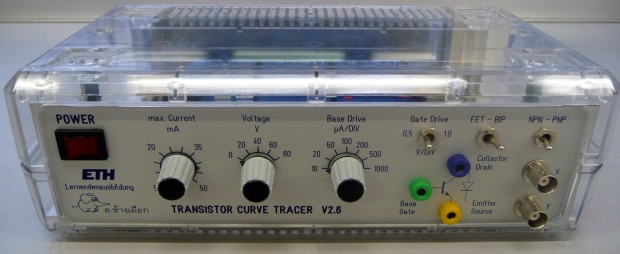
Categories
Statistics
Since 08.08.2014
Counts only, if "DNT = disabled".
216.73.216.233
216.73.216.233
Counts only, if "DNT = disabled".
216.73.216.233
216.73.216.233
Info

เราจะทำแบบวิศวกรผู้ยิ่งใหญ่

28. July 2026
ERRATA
C8 (1µF) is on the schematics but not on the layout. Please add above the 7812.
YOUR OPINION •••
average: 9.000, n: 1

When using this form, your ip is stored in order to avoid multiple voting on the same website. That's it.
When using this form, your ip is stored in order to avoid multiple voting on the same website. That's it.
Curve_Tracer_advanced.php 8553 Bytes 04-03-2025 19:12:33
Curve Tracer Project .:. Part 2
A slightly more advanced version ...
This is the advanced version of the simple Curve Tracer.
It offers a current limiter, and a base/gate Driving Section.
Circuit Description
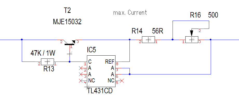
The design is straightforward, the main focus was on easy design. Of course,
an LM-10 would have a lower voltage drop, but the cost is 10 times higher :-(
It follows a relais to switch the polarity. (NPN or PNP).
This voltage is then applied to the collector or drain of the transistor.
This voltages also is the [HORIZONTAL DEFL.]
A shunt (R23,10Ω) in connection with an 10x amplifier (IC2a) amplifies
the voltage drop at the shunt to give a 100mV / 1mA reading. [VERTICAL DEFL.]
The 3rd transformer is used to generate an impulse to trigger the counter (74HC191)
which counts from 0 to 7.
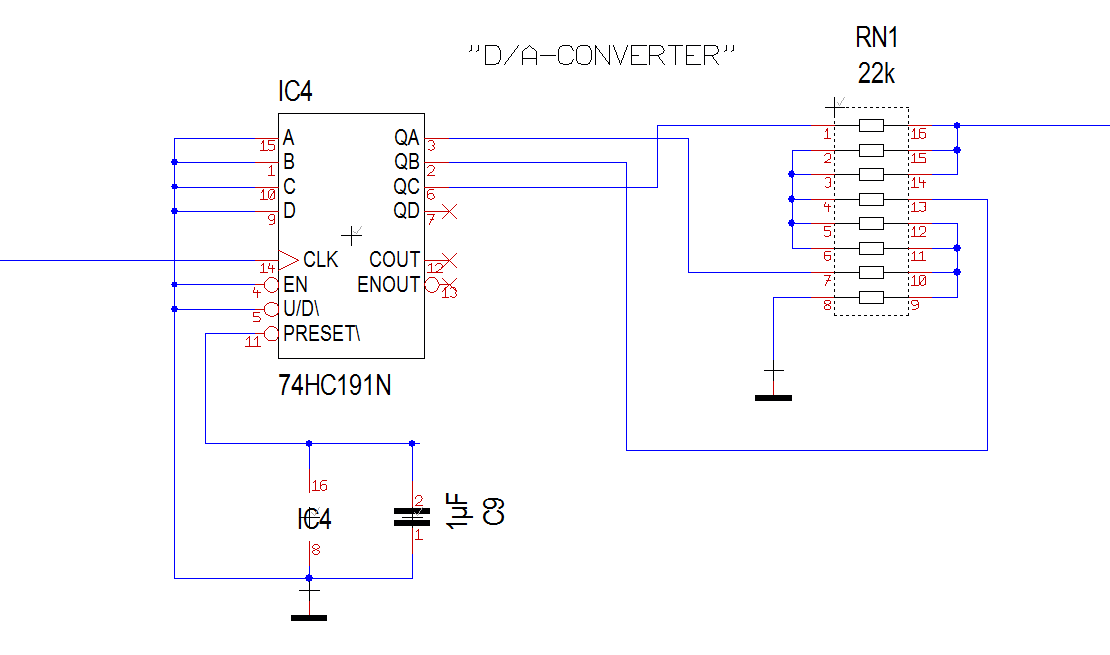
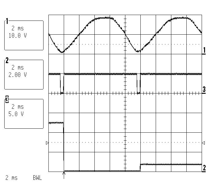
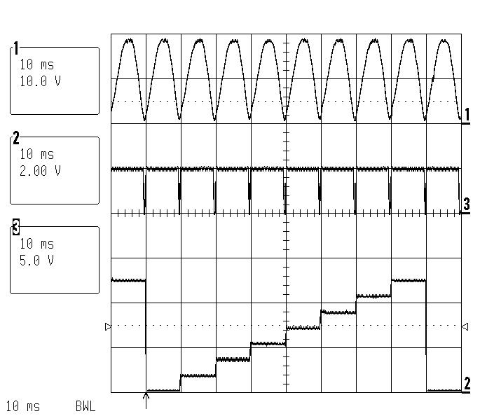
The output of this counter forms with an
R2R-network a staircase which is amplified to 7 Vpp. (adjusted with R20).
This staircase is inverted with IC6a and another relais switches between the
polarity (NPN or PNP). In case a fet is to be analysed, a switch selects
between 0.5 V/DIV and 1.0 V/DIV.
In case a bipolar transitor is to be analysed, a voltage controlled current
source generates the drive current. This is done by IC6c,d.
The 3rd transformer also generates the supply voltages of -12V, +5V, +12V.
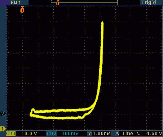
Measurement / Handling
The handling is almost self explanatory. In this section we will show some
measurents and how to obtain them.
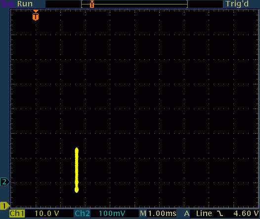
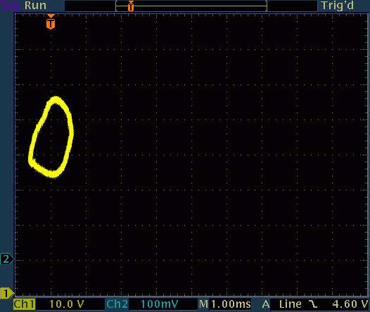
[LEFT] BY 228 Diode [RIGHT] Resistor
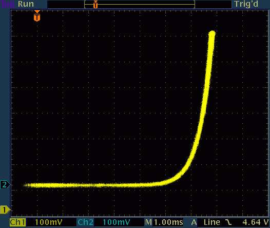
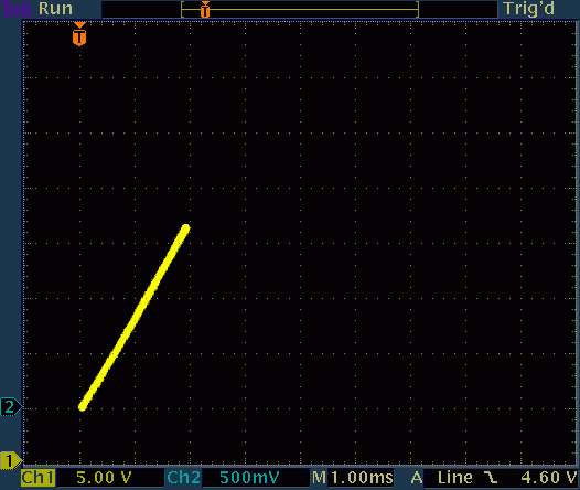
[LEFT] Varistor EPCOS S20K30 [RIGHT] Capacitor 100µF
[LEFT] BY 228 Diode [RIGHT] Resistor
[LEFT] Varistor EPCOS S20K30 [RIGHT] Capacitor 100µF
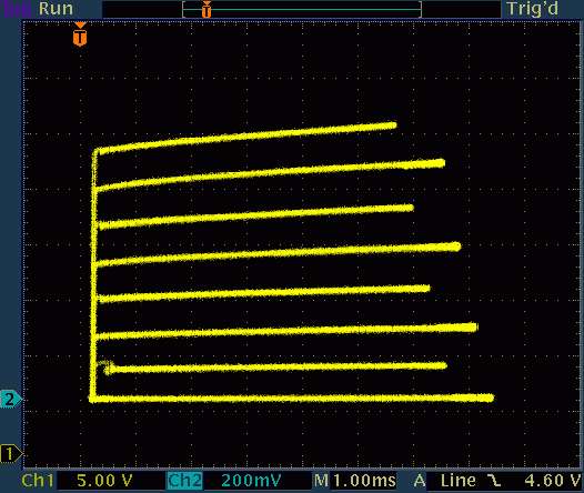
[LEFT] Transformer, primary [RIGHT] BC141-16, Base Drive : 10µA, 40V, 5mA
FAQ
I get a lot of emails concerning R8.
R8 is used to define the current for BJT's. IC4 together with the R2R Network produce a staircase waveform. With R10 this can be adjusted to 1V/step.
IC6d and IC6c generate a current. (I=U/R)
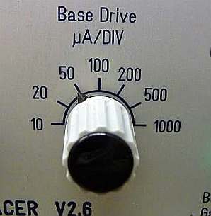
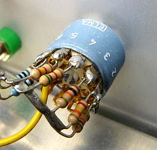
You can use any switch you have. I used one with seven positions to generate a Base Drive of 10-20-50-100-200-500-1000 microAmp /DIV
Therefore I used the following Resistors: 100kR-50kR-20kR-10kR-5kR-2kR-1kR
R8 is used to define the current for BJT's. IC4 together with the R2R Network produce a staircase waveform. With R10 this can be adjusted to 1V/step.
IC6d and IC6c generate a current. (I=U/R)
You can use any switch you have. I used one with seven positions to generate a Base Drive of 10-20-50-100-200-500-1000 microAmp /DIV
Therefore I used the following Resistors: 100kR-50kR-20kR-10kR-5kR-2kR-1kR
✈ Downloads


✈ Share your thoughts
The webmaster does not read these comments regularely. Urgent questions should be send via email.
Ads or links to completely uncorrelated things will be removed.
|
t1 = 7320 d
t2 = 269 ms |
★ ★ ★ Copyright © 2006 - 2026 by changpuak.ch ★ ★ ★
|

|