 ช้างเผือก
Categories
Statistics
Since 08.08.2014
Counts only, if "DNT = disabled".
Your IP is 3.14.80.45
ec2-3-14-80-45.us-east-2.com
Counts only, if "DNT = disabled".
Your IP is 3.14.80.45
ec2-3-14-80-45.us-east-2.com
Info

เราจะทำแบบวิศวกรผู้ยิ่งใหญ่

28. April 2024
Project Details
 Schematics Placement Copper Frontpanel
 Target 3001 File ATMEGA 8 AD 811 EADIP081-CNLED
 Mini PLL Seminar #1 Mini PLL Seminar #2 Mini PLL Seminar #3
nice to know
LIMITATIONS
Due to our Software License we must not allow to use the Target 3001 File for commercial use !
Target 3001 Website
Target 3001 Website
Your valuable opinion :
www.changpuak.ch\
electronics\DCF77.PHP - April 01 2011 19:09:00
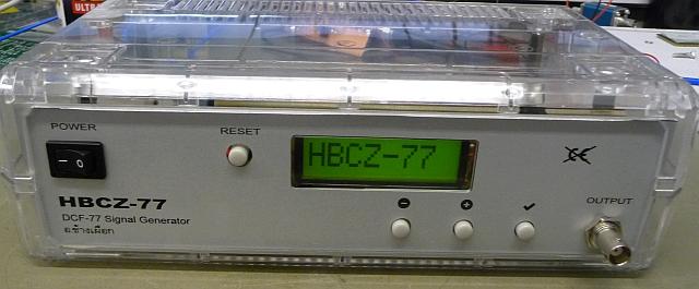
Homebrew DCF-77 Signal Generator
Time machine without the (difficult to obtain) flux capacitor
 WARNING - TRANSMITTING YOUR OWN TIME-SIGNAL IS EVIL.
Well, our meetings take place on wednesdays at 10:30 (sharp). A radio controlled clock is used to determine
whether you are late (and must bring a cake next time) or not. Unfortunately the identical radio controlled clock
in my office always shows a different time :-(
After baking a lot of cakes, I thought about synchronising these disreputable clocks ...
Approach
The straight approach would be to have a crystal oscillator, amplitude modulated by a microprocessor.
As we did promise (2859!) not to abuse the donated crystals for that reason, another approach is used here - which makes
the system even more flexible.
To generate a stable frequency, usually a PLL is used (or DDS). In order to gather some insight in the nature of a PLL,
a small PLL-Demoboard (including a small PLL-Seminar) was designed.
Callsign | Frequency | Modulation | Location |
MSF | 60 kHz | - | Anthorn (United Kingdom) |
HBG | 75 kHz | ASK | Prangins (Switzerland) |
DCF77 | 77.5 kHz | ASK | Frankfurt (Germany) |
TDF | 162 kHz | - | Allouis (France) |
HBCZ77 | 77.5 kHz | ASK | unknown :-) |
Table above : some frequencies, generated easily with jumpers on the PLL-Demoboard ...
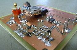
The project uses three PCB's, one for generating the carrier (PLL-Demoboard) and one for the correct (!) modulation of the carrier and one for the Power Supply. As radio controlled clocks use some kind of checking the received codeword
( 30th of February will never be accepted :-) there must be a microprocessor, assuring that the
• PCB#1 may be any clock source of the carrier of your choice. We use the PLL-Demoboard.
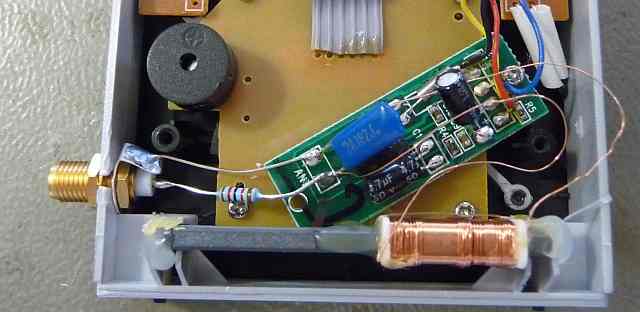
• PCB#2 is the Frontpanel, containing the Microprocessor and ASK Modulator. (Picture below)
• PCB#3 is some kind of Power Supply, delivering +12V...+30V/200 mA and + 5V/100 mA.
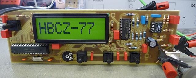
Picture above : The Mainboard, assembled, behind the Frontpanel.
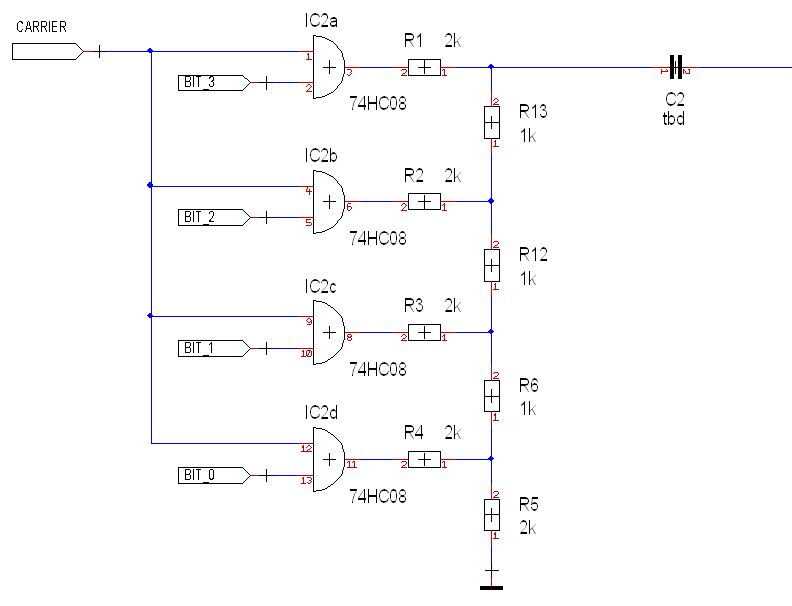
Modulation
The Amplitude Modulation is done with 4 AND-Gates and a R-2R Network. It is therefore possible to modulate the TTL Signal with 16 Steps.
This is somehow cracking a nut with a sledgehammer, but we wanted to present something nifty to comply with the 'educational aspect'.
Note: As we wanted to have a single sided PCB, we reduced this later to 3 Bit.
... and what you see on a Scope
Where a '0' is represented by a 100 ms drop to 25% Amplitude and a '1' drop lasts 200 ms.
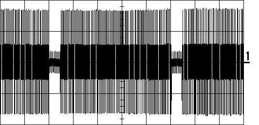
Picture above : Horizontal: 200 ms/DIV, Vertical: 1 V/DIV

DCF77 Time Code (similiar to HBCZ77 Time Code :-)
Bit/Sec. | Meaning | Remarks |
0 | Start of a Minute | always = 0 |
1-14 | reserved / for future use | |
15 | 0=Normal Antenna, 1=Backup Antenna | |
16 | Summer Time Announcement | Set 1 hour before |
17 | Summer Time 0=No, 1=Yes | |
18 | Winter Time 0=No, 1=Yes | |
19 | Leap Second announcement | Set 1 hour before |
20 | Startbit encoded Time | always = 1 |
21 | Minutes, weight = 1 | |
22 | Minutes, weight = 2 | |
23 | Minutes, weight = 4 | |
24 | Minutes, weight = 8 | |
25 | Minutes, weight = 10 | |
26 | Minutes, weight = 20 | |
27 | Minutes, weight = 40 | |
28 | Parity Bit Minutes (even) | Bits 21 - 28 |
29 | Hours, weight = 1 | |
30 | Hours, weight = 2 | |
31 | Hours, weight = 4 | |
32 | Hours, weight = 8 | |
33 | Hours, weight = 10 | |
34 | Hours, weight = 20 | |
35 | Parity Bit Hours (even) | Bits 29 - 34 |
36 | Day of the Month, weight = 1 | |
37 | Day of the Month, weight = 2 | |
38 | Day of the Month, weight = 4 | |
39 | Day of the Month, weight = 8 | |
40 | Day of the Month, weight = 10 | |
41 | Day of the Month, weight = 20 | |
42 | Day of the Week, weight = 1 | Monday = 1 |
43 | Day of the Week, weight = 2 | Tuesday = 2 |
44 | Day of the Week, weight = 4 | Wednesday = 3 |
45 | Number of the Month, weight = 1 | |
46 | Number of the Month, weight = 2 | |
47 | Number of the Month, weight = 4 | |
48 | Number of the Month, weight = 8 | |
49 | Number of the Month, weight = 10 | |
50 | Year, weight = 1 | ( 00 - 99 ) |
51 | Year, weight = 2 | |
52 | Year, weight = 4 | |
53 | Year, weight = 8 | |
54 | Year, weight = 10 | |
55 | Year, weight = 20 | |
56 | Year, weight = 40 | |
57 | Year, weight = 80 | |
58 | Parity Bit Date (even) | Bits 36 - 57 |
59 | Minute Sync | Carrier unmodulated |
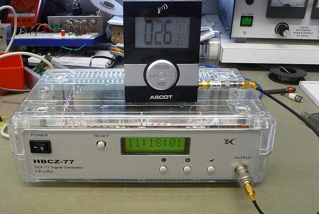
Putting it all together ...
A radio controlled clock is modified therefore, that the generated Signal is fed directly into the
Amplifier following the Antenna. (Decoupling with an 1 kΩ Resistor).
It is assumed, that the portion radiated through the Antenna is very small, as we use an
Attenuator of 30 dB. (and of course operate it in a fully shielded room :-)
Connecting the Signal Generator to the Clock - using a DC-Block and a 30 dB Attenuator from
Mini Circuits - the Situation is as follows :
✈ Share your thoughts
The webmaster does not read these comments regularely. Urgent questions should be send via email.
Ads or links to completely uncorrelated things will be removed.
Your Browser says that you allow tracking. Mayst we suggest that you check that DNT thing ?
|
t1 = 6499 d
t2 = 331 ms |
★ ★ ★ Copyright © 2006 - 2024 by changpuak.ch ★ ★ ★
|

|