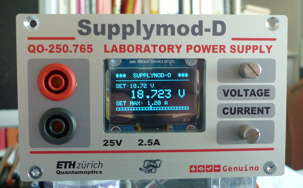
A Voltage Supply, 25 V, 2.5 A, with Arduino Nano Every
The Prototype
✈ Motivation
This is a Power Supply using the LM2576 (Power Converter 3-A Step-Down Voltage Regulator) with an additional Lowpass
Filter and a Current Limiting circuit. (As requested by our physicists). It can be controlled (Voltage) remotely by USB.
This one overcomes the usual limit of Vmin = Vref by introducing a negative auxiliary voltage.
✈ The Design
The design uses the LM2576 with a twist. Its GND is not connected to GND, but instead, a negative
Voltage of - 1.25 V is generated (LM337) and offsets the feedback circuit. By that, the
output voltage can go down to 0 V.
An Arduino Nano Every does the housekeeping. It programs a DAC (AD5693RARMZ) to generate a voltage
from 0 ... +2.5 V. This voltage is compared to the downscaled output voltage by the LM2576.
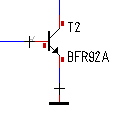
The output is handled by the driver (BUF634F/500 or LME49600). If the load calls for more current, the voltage drop
across R1 (10 Ω * 65 mA ≈ 0.65 V) gets larger and therefore increases the Base-Emitter Voltage of the Power Transistors.
They (TIP2955 or TIP3055) then start conducting and take over gradually. They are mounted at the bottom of the case,
so the case has to dissipate a maximum of 15 V * 0.5 A = 7.5 W.
The current is measured with a 50 mΩ shunt. This voltage drop is amplified by a factor of 50 and biased around 2.5 V
to be suiteable for an Arduino analog input. For this, the positive input of the opamp is biased at 50 mV. The
resistors for the opamp are chosen to be 100 kΩ and 2 kΩ (GAIN = 50). The voltage divider at the
positive input uses 33 kΩ and 680 Ω.
We used this
calculator for that.
RACM30-15DK/277 handling that powerline thingThe TIP3055/2955 use the case as heatsink
✈ Downloads
✈ Special Components used here
ITEM
SUPPLIER
Cable for USB
Adafruit #937, Panel Mount - B Female to Micro-B Male
COM SETTINGS :
Set up the COM port inside the PC according to the following list.
• Baud rate: 115200
• Parity bit: None
• Data bit: 8
• Stop bit: 1
• Data flow control: None
COMMAND SYNTAX : VSET:xx.x OR VSET:x.x
Description: Sets the output voltage.
Example VSET:9.99
Sets the voltage to 9.99 V
Returns O.K.
IOUT?
Description:Returns the actual output current.
Example IOUT?
Returns the output current.
*IDN?
Description:Returns the Devices identification.
Example *IDN?
Returns Supplymod-D V2.0 BY CHANGPUAK.CH (C) 07/2025
✈ Performance
Drift
The voltage drift is mainly introduced by the DAC's internal voltage reference, multiplied by 5.
The datasheet of the AD5693R states a typical 2 ppm/°C and a maximum of 5 ppm/°C. The dac
was programmed to 9.299 V, Current drawn 500 mA. Within 47 Minutes, an increase
of ≈ 1 mV was observed.
Response to Load Changes. Step from 90 mA to 450 mA
The Power Supply needs about 200 ms to regulate for jumps in load changes. This is mainly caused
by the relatively large capacitor C12 (1nF).
✈ Share your thoughts
The webmaster does not read these comments regularely. Urgent questions should be send via email.
Ads or links to completely uncorrelated things will be removed.
 ช้างเผือก