 ช้างเผือก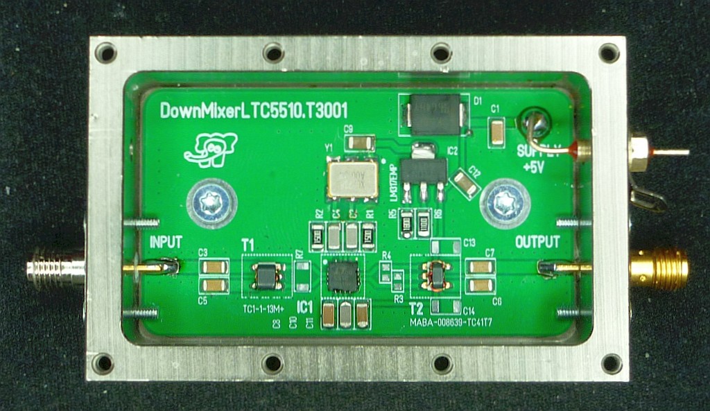
Categories
Statistics
Since 08.08.2014
Counts only, if "DNT = disabled".
216.73.216.212
216.73.216.212
Counts only, if "DNT = disabled".
216.73.216.212
216.73.216.212
Info




เราจะทำแบบวิศวกรผู้ยิ่งใหญ่
12. October 2026
YOUR OPINION •••
average: 0.001, n: 0

When using this form, your ip is stored in order to avoid multiple voting on the same website. That's it.
When using this form, your ip is stored in order to avoid multiple voting on the same website. That's it.
DownConverter_for_SDR_Callisto_ea.php 8691 Bytes 16-09-2026 17:24:37
DownConverter for SDR, Callisto e.a.
Using the LTC5510, XLP736A00.000000I and some coworkers
The Prototype - R3,R4,R7 to be optimised
✈ Specifications
| PARAMETER | REMARKS |
| Supply | + 5 V, 250 mA |
| Input | 1000.1 - 1999.9 MHz |
| Output | 0.1 ... 999.9 MHz |
✈ The Workhorse : LTC5510 from Linear Technology
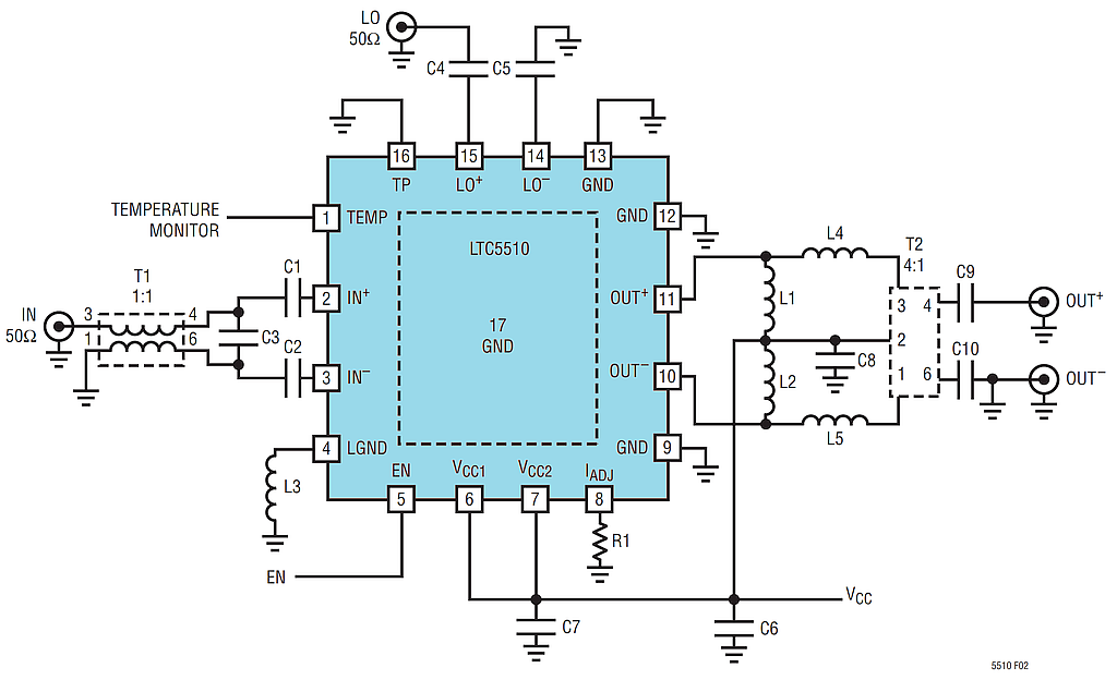
Test Circuit, drawing coutesy of Analog Devices
The datasheet says "The LTC5510 is a high linearity mixer optimised for applications requiring very wide input bandwidth, low distortion, and low LO leakage. The chip includes a double-balanced active mixer with an input buffer and a high speed LO amplifier. The input is optimised for use with 1:1 transmissionline baluns, allowing very wideband impedance matching. The mixer can be used for both up- and down-conversion and can be used in wideband systems." here, we use it for downconversion. The LO used is a XLP736A00.000000I (The Renesas XL devices - XO and VCXO options - are ultra-precision crystal oscillators with 750 to 890 fs typical phase jitter over 12 kHz to 20 MHz bandwidth.) running at 1000 MHz.
✈ LTC5510 - that current adjustment thing
Pin 8 - Bias Adjust Pin. This pin allows adjustment of the internal mixer current by adding an external
pulldown resistor. The typical DC voltage on this pin is 1.8 V. If not used, this pin must be left floating.
As we use a Vcc of 5.0 V and the output range is below 1.2 GHz, according to Table 7 in the datasheet,
the recommended Values for R1 is "open".
✈ BOM - Bill Of Materials
The assembled PCB will cost approximately € 25.- (2026)
| Component | Price [€] | Distributor |
| SK56C | 0.285 | Mouser |
| XLP736A00.000000I | 3.74 | Mouser |
| LTC5510IUF#PBF | 10.89 | Mouser |
| LM317EMP | 1.42 | Mouser |
| TC1-1-13M+ | 3.29 | Mouser |
| MABA-008639-TC41T7 | 1.42 | Mouser |
| 12 x Capacitor à 0.20 | 2.40 | ... |
| 7 x Resistor à 0.10 | 0.70 | ... |
✈ The Local Oscillator : XLP736A00.000000I - 1 GHz LVPECL XCO
The only thing to mention here is, that this is a LVPECL thing. This means Low-Voltage Positive Emitter-Coupled Logic.
So we have to use resistors at the output (Emitter) to create a voltage. (typically 700 mV to 800 mV peak-to-peak).
As we use ac coupling and don't need to meet logic level restrictions, we can get away with just two resistors
connected to ground - we have chosen 2 x 150 Ω (resulting in about 10 mA of Bias Current) and of course
two capacitors (100 pF each). The input impedance of the LTC5510 (LO+ and LO- each) is internally matched to
50 Ω so this is clearly not matched for maximum Power. But the traces are very short with respect to
the wavelength, so we don't care that much.
✈ Performance
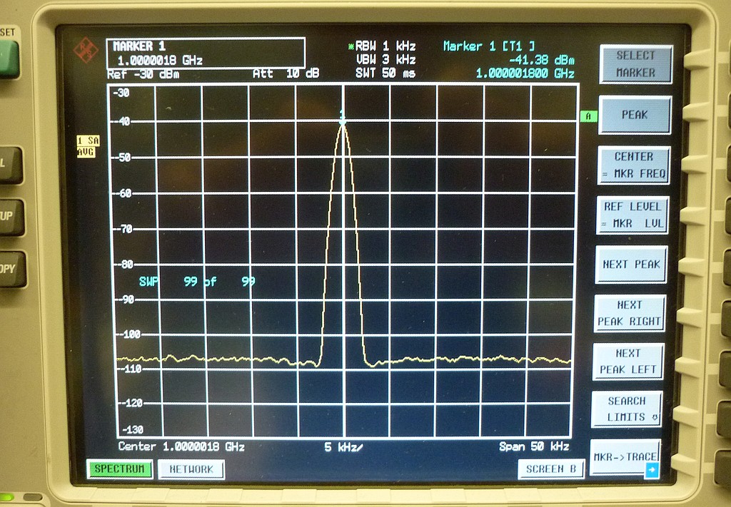
LO Feedthru, as seen at the output
✈ Downloads

✈ Share your thoughts
The webmaster does not read these comments regularely. Urgent questions should be send via email.
Ads or links to completely uncorrelated things will be removed.
|
t1 = 7396 d
t2 = 250 ms |
★ ★ ★ Copyright © 2006 - 2026 by changpuak.ch ★ ★ ★
|
|


